Eletromagnetic stirring supporting roller

A technology of electromagnetic stirring and supporting rolls, which is applied in the field of metallurgical continuous casting equipment, can solve the problems of reducing electromagnetic stirring force, slab bulging deformation, and affecting the quality of slab, so as to prolong service life, reduce deflection deformation, and reduce maintenance volume effect

Active Publication Date: 2009-06-10
CHINA NAT HEAVY MACHINERY RES INSTCO
View PDF0 Cites 9 Cited by
  • Summary
  • Abstract
  • Description
  • Claims
  • Application Information

AI Technical Summary

Problems solved by technology

Since the shape of the stirring roll is an integral roll supported by two points, and the fine rolls of the continuous casting machine require the electromagnetic stirring roll to be as thin as possible. The roller will be deflected and deformed, which will affect the normal work and life of the stirring roller. At the same time, the slab will appear bulging deformation, which will directly affect the quality of the slab.
In order to solve the above problems, at present, the rigidity of the stirring roller is increased by dividing the whole roller into two sections and increasing the bearing seat. However, this method greatly reduces the electromagnetic stirring force and increases the maintenance of the equipment, which seriously restricts the electromagnetic stirring. wide application of

Method used


Image

  • Eletromagnetic stirring supporting roller
  • Eletromagnetic stirring supporting roller
  • Eletromagnetic stirring supporting roller

Examples


Embodiment Construction

[0015] The structural principle and working principle of the present invention will be described in detail below in conjunction with the accompanying drawings.

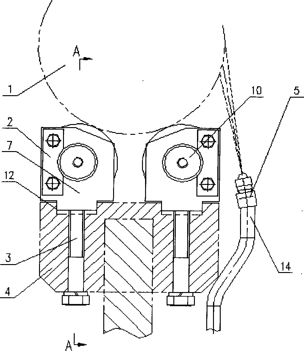
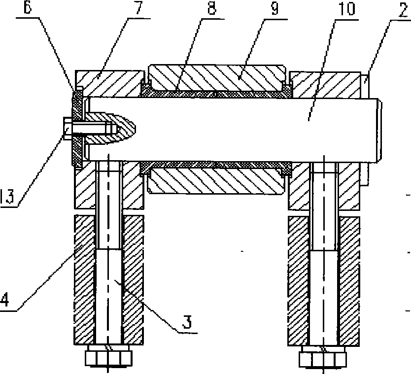
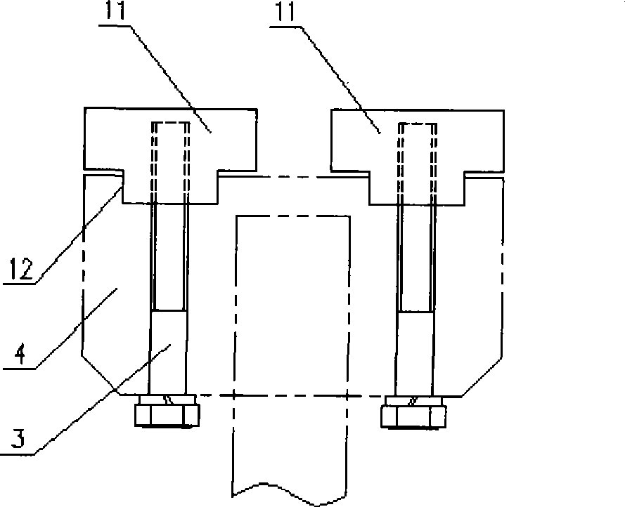
[0016] refer to figure 1 , figure 2 , an electromagnetic stirring support roller device, installed on the bottom of the stirring roller 1, including a support roller 9, the support roller 9 is installed in the notch 12 of the inner and outer arc frame 4 of the sector, and the notch 12 and the protruding part of the bearing seat 7 adopt Clearance fit, and fixed on the frame 4 with high-strength bolts 3, the support roller 9 penetrates the mandrel 10 in the middle and is assembled with the bearing seat 7, and one end of the mandrel 10 is connected with the bearing seat 7 through the end cover 6 and the bolt 13 to prevent The mandrel 10 moves relative to the bearing seat 7; the other end uses the shaft end baffle 2 to fix the mandrel 10 to prevent axial movement and rotation. A high-strength self-lubricating bearing 8...


PUM


Abstract

The invention provides an electromagnetic stirring support roller device, which is arranged at the bottom of a stirring roller 1, and comprises a supporting roller 9 arranged in a notch 12, the notch 12 is in clearance fit with a bearing seat 7 and is fixed on a framework 4 through a high strength bolt 3, the middle of the support roller 9 is inserted with a mandril 10 and assembled together with the bearing seat 7, one end of the mandril 10 is connected with the bearing seat 7 through an end cover 6 and a bolt 13, and the other end of the mandril 10 is fixed with the mandril 10 through a shaft end baffle 2, a high-strength self-lubricating bearing 8 is arranged between the support roller 9 and the mandril 10, and a water spraying rack 14 on the inner and outer arc framework 4 is provided with a washing nozzle 5 specially. When the stirring roller 1 rotates, the support roller 9 is driven to rotate, then the washing nozzle 5 washes off iron scale on the stirring roller 1; when the stirring roller 1 is not used, a pressing plate 11 can be mounted in a mounting notch 12 of the support roller 9 for protection. The electromagnetic stirring support roller device has the characteristics of strengthening the rigidity, reducing the deflection deformation of the stirring roller, improving the stirring force, prolonging the service life of the stirring roller and reducing maintenance quantity.

Description

technical field [0001] The invention relates to a metallurgical continuous casting equipment, in particular to an electromagnetic stirring support roller device. Background technique [0002] In order to increase the equiaxed grain rate, improve the internal quality of the slab, and improve the product grade of the continuous casting machine, the electromagnetic stirring technology is gradually widely used in the continuous casting machines of various domestic steel mills, and the electromagnetic stirring roller, that is, the roller stirrer, is one of them. Since the shape of the stirring roll is an integral roll supported by two points, and the fine rolls of the continuous casting machine require the electromagnetic stirring roll to be as thin as possible. The roll will be deflected and deformed, which will affect the normal work and life of the stirring roll. At the same time, the slab will be deformed, which will directly affect the quality of the slab. In order to solve...

Claims


Application Information

Patent Timeline
Patent Type & Authority Applications(China)
IPC IPC(8): B22D11/115
Inventor 王西林田进刘赵卫
Owner CHINA NAT HEAVY MACHINERY RES INSTCO
Why Eureka
Try Eureka