Magnetizer for fluid/gas pipes or liquid/gas grooves

A magnetizing device and gas pipeline technology, applied in water/sludge/sewage treatment, magnetic field/electric field water/sewage treatment, combustion air/combustion-air treatment, etc. Stability and other issues, to achieve the effect of stable magnetic field range and direction, not easy to fail and accident, convenient installation and setting

Inactive Publication Date: 2009-06-10
卢国华
View PDF1 Cites 6 Cited by
  • Summary
  • Abstract
  • Description
  • Claims
  • Application Information

AI Technical Summary

Problems solved by technology

[0007] 2. The alternating magnetic field generated by the coil is relatively sparse and unstable, and it is difficult to control the change of its magnetic field. It cannot completely magnetize all the passing water, so the effect of magnetization is not obvious, and it is difficult to specify the direction due to the coil magnetic field The impact of the limited range of use, easy to interfere or magnetize other items
[0008] 3. The high-frequency current of the high-frequency current source is limited by its frequency, and its use range is limited, so it cannot be widely used, and the overall energy consumption is quite high, wasting energy

Method used


Image

  • Magnetizer for fluid/gas pipes or liquid/gas grooves
  • Magnetizer for fluid/gas pipes or liquid/gas grooves
  • Magnetizer for fluid/gas pipes or liquid/gas grooves

Examples


Embodiment Construction

[0052] The present invention will be further described in detail below in conjunction with the accompanying drawings and embodiments.

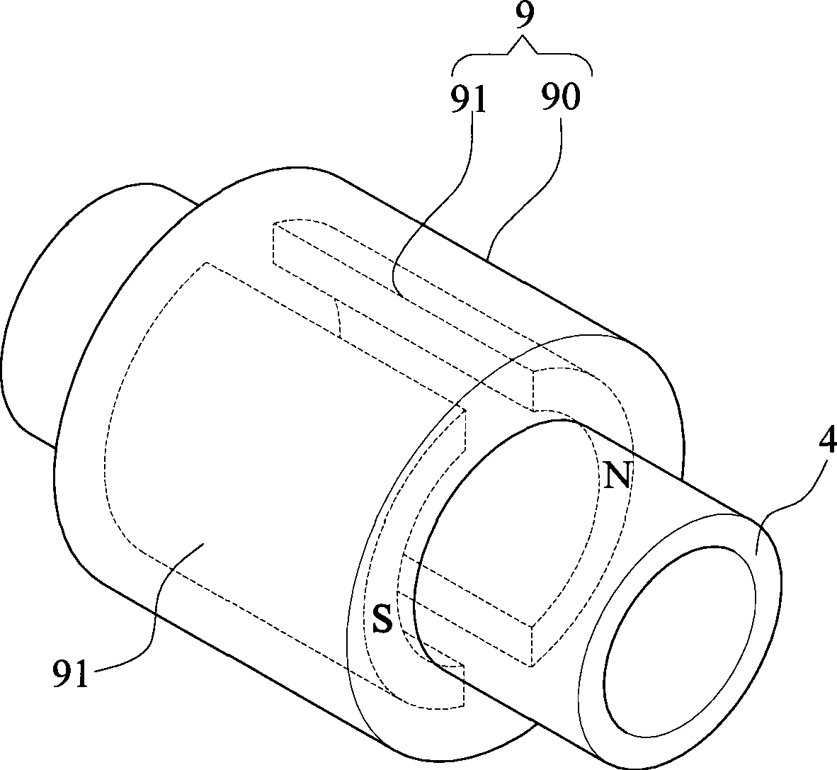
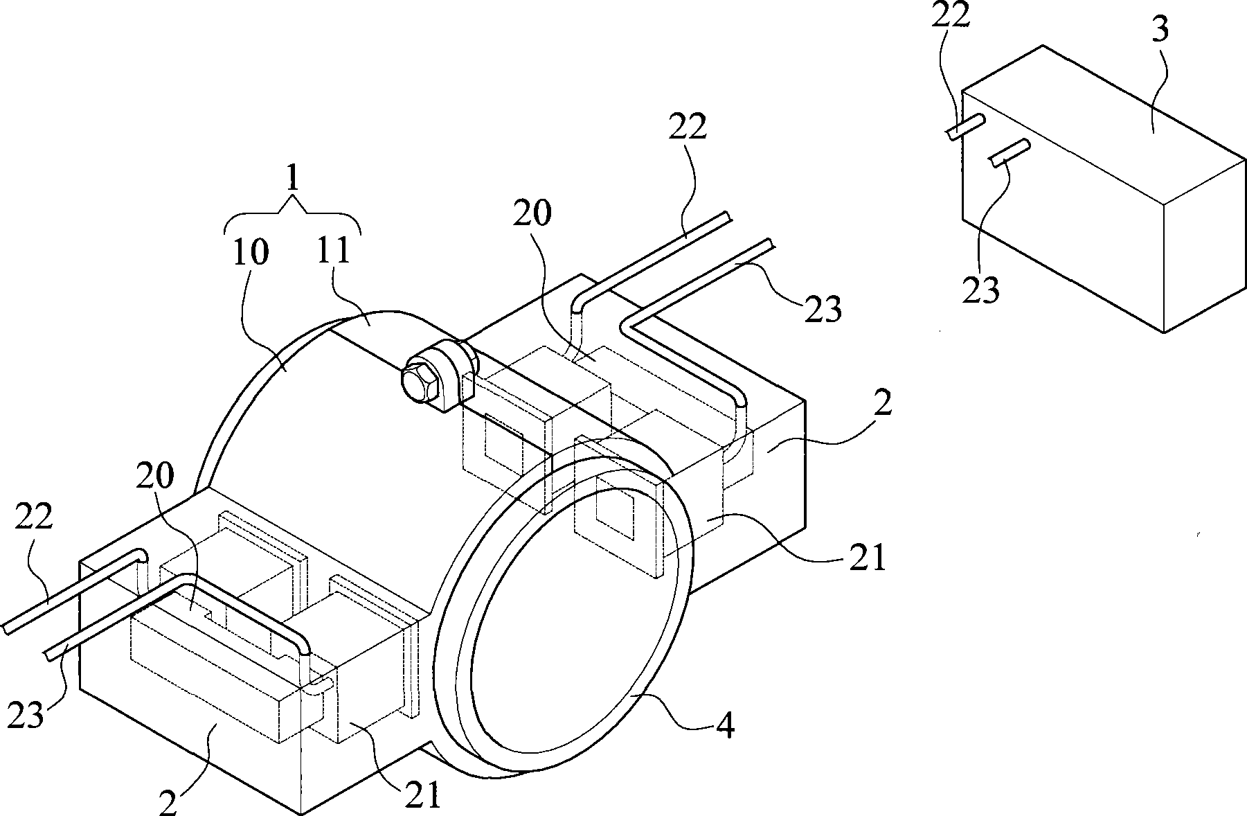
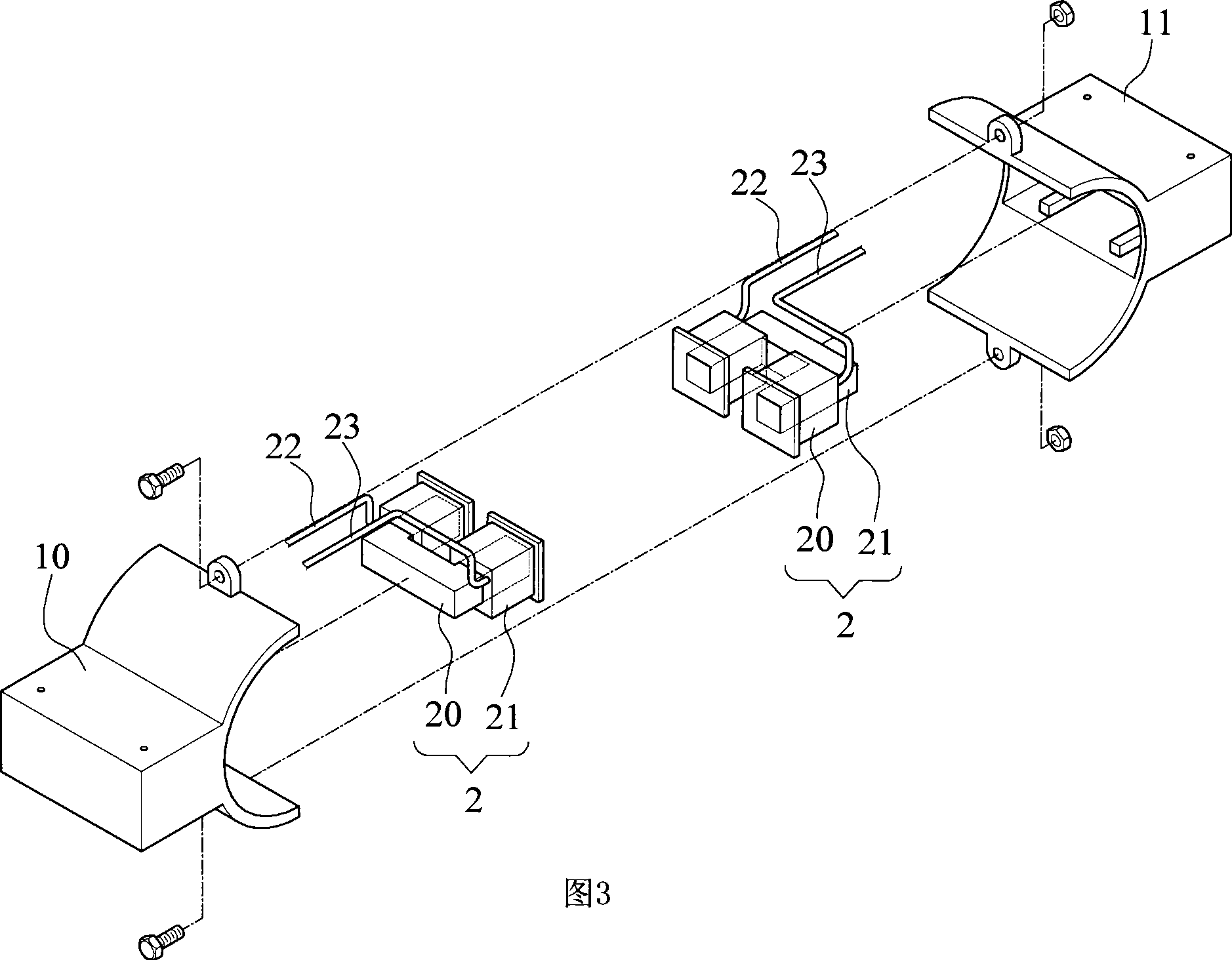
[0053] like figure 2 Shown is a three-dimensional schematic view of the first embodiment of the present invention, as shown in Figure 3 is a three-dimensional exploded view of the magnetization device of the first embodiment of the present invention, such as Figure 5 ˜ FIG. 8 are three-dimensional schematic diagrams of the second to fifth embodiments of the present invention, and FIG. 9 is a partially enlarged schematic diagram of FIG. 8 .

[0054] The figure reveals that a magnetizing device for a liquid / gas pipeline or a liquid / gas tank is characterized in that it comprises:

[0055] A shell 1 arranged outside the liquid / gas pipeline or the liquid / gas tank;

[0056] At least two or more electromagnetic devices 2 are arranged in the aforementioned casing 1 and are in contact with the liquid / gas pipeline or the outer wall of the liquid / gas...


PUM

PropertyMeasurementUnit
electric potential / voltageaaaaaaaaaa

Abstract

The purpose of the invention is to provide a magnetizer for liquid / gas pipe or liquid / gas tank capable of improving burning efficiency or washing effect after refining the liquid or gaseousness molecular group in the tube or tank. The technical means comprises: a housing ( 1 ) provided out the liquid / gas pipe or liquid / gas tank; at least two electromagnetic (EM) devices ( 2 ) provided in the housing (1) in contact with an outer surface of a pipe or tank, the EM device ( 2 ) includes a U-shaped magnetic conduit ( 20 ) with two solenoids ( 21 ) disposed at both ends of the conduit ( 20 ), and a power supplier ( 3 ) transfers direct current (DC) into alternate current (AC) or directly provides AC for inducing time-varying magnetic flux lines.

Description

technical field [0001] The invention relates to a magnetizing device used in a liquid / gas pipeline or a liquid / gas tank. Background technique [0002] Traditional magnetization devices such as figure 1 Shown is a schematic diagram of an old-style magnetizing device. The magnetizing device 9 is composed of a housing 90 and magnets 91 inside the two housings 90, which can magnetize the material in the pipeline 4 and improve functionality. However, the general magnets 91 all have the problems of non-uniform magnetic force lines, insufficient strength, and limited range. [0003] Therefore, those in the industry have made further improvements to the above problems. As shown in the following patent document 1, a device for magnetizing water is characterized in that: the device has a high-frequency current source for generating high-frequency current and outputting it to the coil. An alternating magnetic field is formed in the coil to magnetize the water passing through the magn...

Claims


Application Information

Patent Timeline
Patent Type & Authority Applications(China)
IPC IPC(8): C02F1/48
CPCF02M27/045C02F1/005C02F1/48
Inventor 卢国华
Owner 卢国华
Why Eureka
Try Eureka