Conveying apparatus and transmitting system

a transmission system and conveying apparatus technology, applied in the direction of conveyors, rollers, dynamo-electric machines, etc., can solve the problems of unstable movement along the first direction, and achieve the effects of reducing the above force component, increasing the stability of movement along the first direction, and reducing the number of magnetic gears

Active Publication Date: 2018-07-26
ABB (SCHWEIZ) AG
View PDF1 Cites 7 Cited by
  • Summary
  • Abstract
  • Description
  • Claims
  • Application Information

AI Technical Summary

Benefits of technology

[0005]The structure of the conveying apparatus effectively suppresses particles such as those generated by mechanical gear transmission. Second, one power source can be used so that a plurality of the first magnetic gears arranged non-coaxially are rotated synchronously; therefore, no additional control member is needed, enhancing the stability of the conveying apparatus and reducing the complexity of the system.
[0007]The use of straight-teeth magnetic racks would cause the movement along the first direction unstable for the reason that they are subject to a force component perpendicular to the first direction. By designing the first magnetic gear and the second magnetic gear as bevel gears and designing the magnetic rack as a bevel rack, the above force component may be reduced, such that the straight-teeth magnetic rack will cause movement along the first direction more stable. As an alternative, the first magnetic gear and the second magnetic gear may be designed as conical gears; moreover, the magnetic rack is designed as a straight rack. By adopting the conical magnetic rack, a force component perpendicular to the first direction may be reduced, such that the straight-teeth magnetic rack will cause movement along the first direction more stable.
[0008]According to another aspect of the present invention, there is provided a conveying apparatus, including: a magnetic rack movable along a first direction, having a plurality of magnetic rack magnetic teeth arranged in a first direction, adjacent ones of the magnetic rack magnetic teeth having different polarities; at least one first magnetic gear coaxially arranged, rotatable about at least one first axis, respectively, wherein each magnetic gear has a plurality of first magnetic gear magnetic tooth and adjacent ones of the first magnetic gear magnetic teeth have different polarities; wherein: the first axis and the first direction are arranged substantially in parallel with each other; the plurality of magnetic rack magnetic teeth may engage with the plurality of first magnetic gear magnetic teeth in a non-contact state; and when the at least one first magnetic gear is used as a driving gear to output power, the power may be transmitted to the at least one first magnetic gear via the at least one first magnetic gear so as to move it along the first direction. Based on this solution, the number of magnetic gears can be reduced, costs are reduced, the structure is simplified, and space is saved.
[0009]According to another aspect of the present invention, there is provided a transmitting system, including: a first conveying apparatus employing one of the conveying apparatus structures; and a second conveying apparatus employing one of the conveying apparatus structures; wherein a first direction of the first conveying apparatus and a first direction of the second conveying apparatus are substantially parallel with each other; the magnetic rack magnetic teeth of the first conveying apparatus and the magnetic rack magnetic teeth of the second conveying apparatus are arranged in a splayed form. In this way, the magnetic force F applied on the magnetic rack of the first conveying apparatus and the magnetic rack of the second conveying apparatus counteract against each other, and change of a substrate in a direction perpendicular to the first direction is small, and thus a steady gesture can be maintained.

Problems solved by technology

The use of straight-teeth magnetic racks would cause the movement along the first direction unstable for the reason that they are subject to a force component perpendicular to the first direction.

Method used


Image

  • Conveying apparatus and transmitting system
  • Conveying apparatus and transmitting system
  • Conveying apparatus and transmitting system

Examples


Embodiment Construction

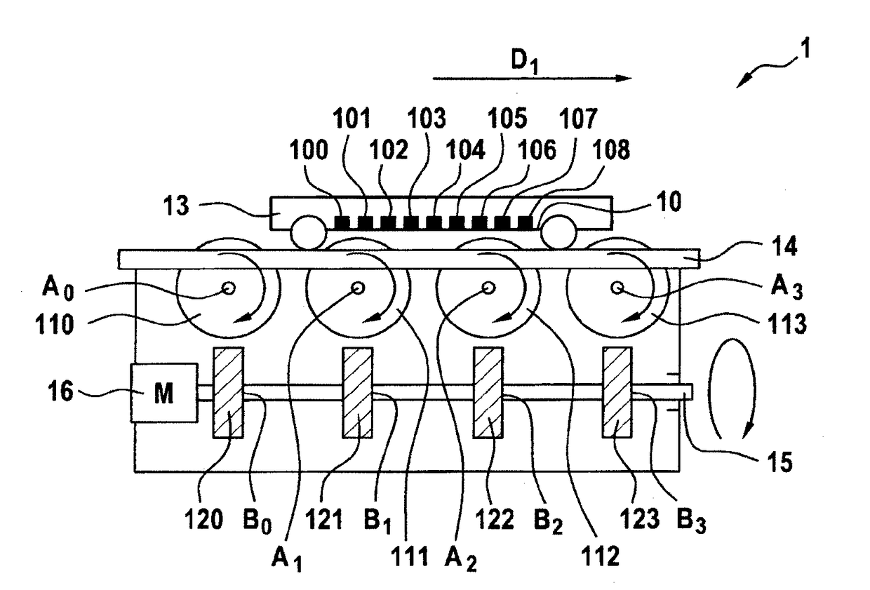
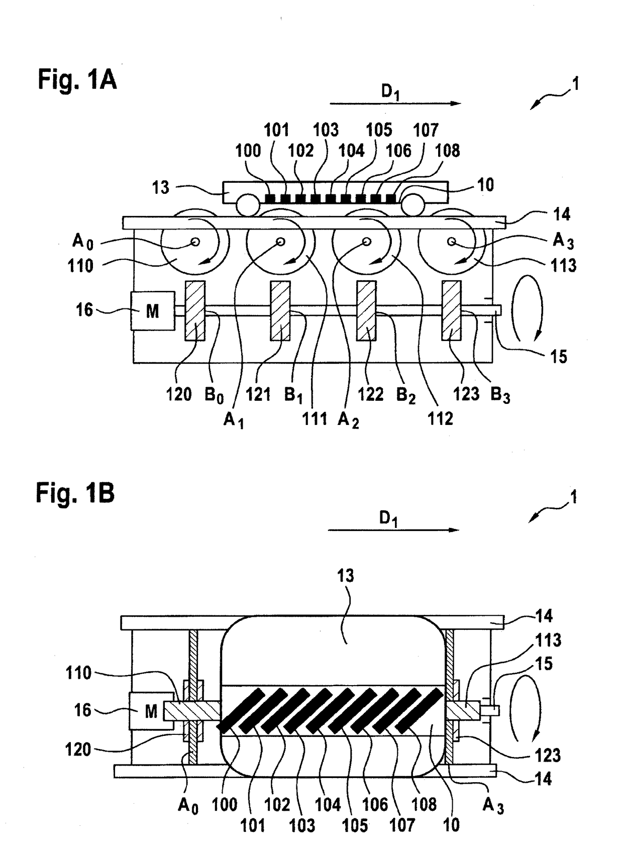
[0021]FIGS. 1A and 1B illustrate a main view and a top view of a conveying apparatus according to one embodiment of the present invention. As illustrated in FIGS. 1A and 1B, the conveying apparatus 1 includes: a magnetic rack 10, at least one first magnetic gear 110-113, and at least one second magnetic gear 120-123. The magnetic rack 10 may move along a first direction D1. For example, the magnetic rack 10 may be fixed on the substrate 13 and the substrate 13 is rolling connected to a guide rail 14 arranged in the first direction D1, such that the magnetic rack 10 may move on the guide rail 14 with the substrate 13 along the first direction D1. A to-be-conveyed material is placed on the substrate 13. With the rolling connection, particles generated by contact with the guide rail 14 can be reduced. The magnetic rack 10 further includes a plurality of magnetic rack magnetic teeth 100-108 arranged along the first direction D1, and adjacent ones of the magnetic rack magnetic teeth have...


PUM


Abstract

The present disclosure provides a conveying apparatus and a transmitting system. The conveying apparatus includes: a magnetic rack movable along a first direction, having a plurality of magnetic rack magnetic teeth arranged in the first direction, adjacent ones of the magnetic rack magnetic teeth having different polarities; at least one first magnetic gear rotatable about at least one first axis, respectively, wherein each first magnetic gear has a plurality of first magnetic gear magnetic teeth and adjacent ones of the first magnetic gear magnetic teeth have different polarities; at least one second magnetic gear rotatable about at least one second axis, wherein each second magnetic gear has a plurality of second magnetic gear magnetic teeth and adjacent ones of the second magnetic gear magnetic teeth have different polarities; wherein: at least one first magnetic gear, in combination with at least one second magnetic gear, forms at least one magnetic gear set, respectively; the magnetic rack and second magnetic gear may magnetically engage in a non-contact state with different first magnetic gear teeth of the first magnetic gear belonging to the same magnetic gear set via the magnetic rack magnetic teeth and the second magnetic gear teeth, respectively; and when the at least one second magnetic gear is used as a driving gear to output power, the power may be transmitted to the magnetic rack through at least one first magnetic gear so as to move it along the first direction.

Description

FIELD OF THE INVENTION[0001]The present invention relates to a conveying apparatus and a transmitting system, and more specifically, to a conveying apparatus and a transmitting system using magnetic force.BACKGROUND OF THE INVENTION[0002]In Computer, Communication and Consumer (3C) industries, a product needs to be assembled in a dustless environment. For example, as far as screen assembly is concerned, in order to achieve a higher dustless degree, a screen panel needs to be carried and conveyed by a supporting member in a clean room. Generally, the supporting member is driven by a rack-pinion mechanism through mechanical engagement or driven by a belt, a roller, and a link plate through friction. In this case, particles generated by mechanical engagement or friction cannot be ignored.[0003]In order to reduce the particles, the Patent JPS619104A discloses a material conveying system for a clean room. The system includes an electromagnet that may travel along a guide rail, and a tray...

Claims


Application Information

Patent Timeline
Patent Type & Authority Applications(United States)
IPC IPC(8): B65G54/02B65G13/04B65G23/23
CPCB65G54/02B65G13/04B65G23/23H02K49/102
Inventor GU, HAOCHI, ZHAOFUYANG, JIBO
Owner ABB (SCHWEIZ) AG
Why Eureka
Try Eureka