
Supporting member and electronic apparatus

Inactive Publication Date: 2012-07-26
PANASONIC CORP
View PDF4 Cites 6 Cited by
  • Summary
  • Abstract
  • Description
  • Claims
  • Application Information

AI Technical Summary

Benefits of technology

[0011]The disclosure of the present Application makes it possible to minimize disproportions in the resting contact state of the multiple foot sections and stabilize the orientation of the electronic apparatus.

Problems solved by technology

When the enclosure of an apparatus is made thinner, the application of strong impacts or pressure from the outside may result in plastic deformation, and when the enclosure undergoes plastic deformation, disproportions may occur in the resting contact state of the multiple rubber feet, i.e. some of the rubber feet may be moved out of resting contact, etc.
When an electronic apparatus is placed on a tabletop, etc., its orientation becomes unstable if disproportions occur in the resting contact state of the rubber feet.
However, in the configurations disclosed in the above-described two Patent Documents, deformation of the enclosure of the tabletop apparatus as a result of external pressure and the like causes disproportions to occur in the resting contact state of the multiple adjustable feet and the orientation of the tabletop apparatus becomes unstable.
In addition, in the adjustable foot disclosed in Patent Document 2, the height or number of steps (N steps) that can be adjusted is fixed and it is difficult to get rid of disproportions in the resting contact state of the multiple adjustable feet.

Method used


Image

  • Supporting member and electronic apparatus
  • Supporting member and electronic apparatus
  • Supporting member and electronic apparatus

Examples


embodiment 1

1. Configuration of the Electronic Apparatus

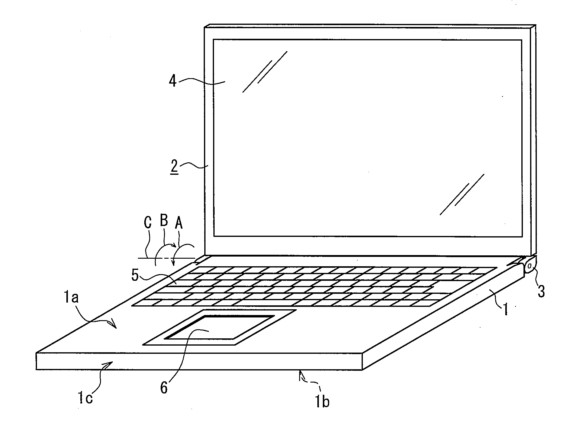
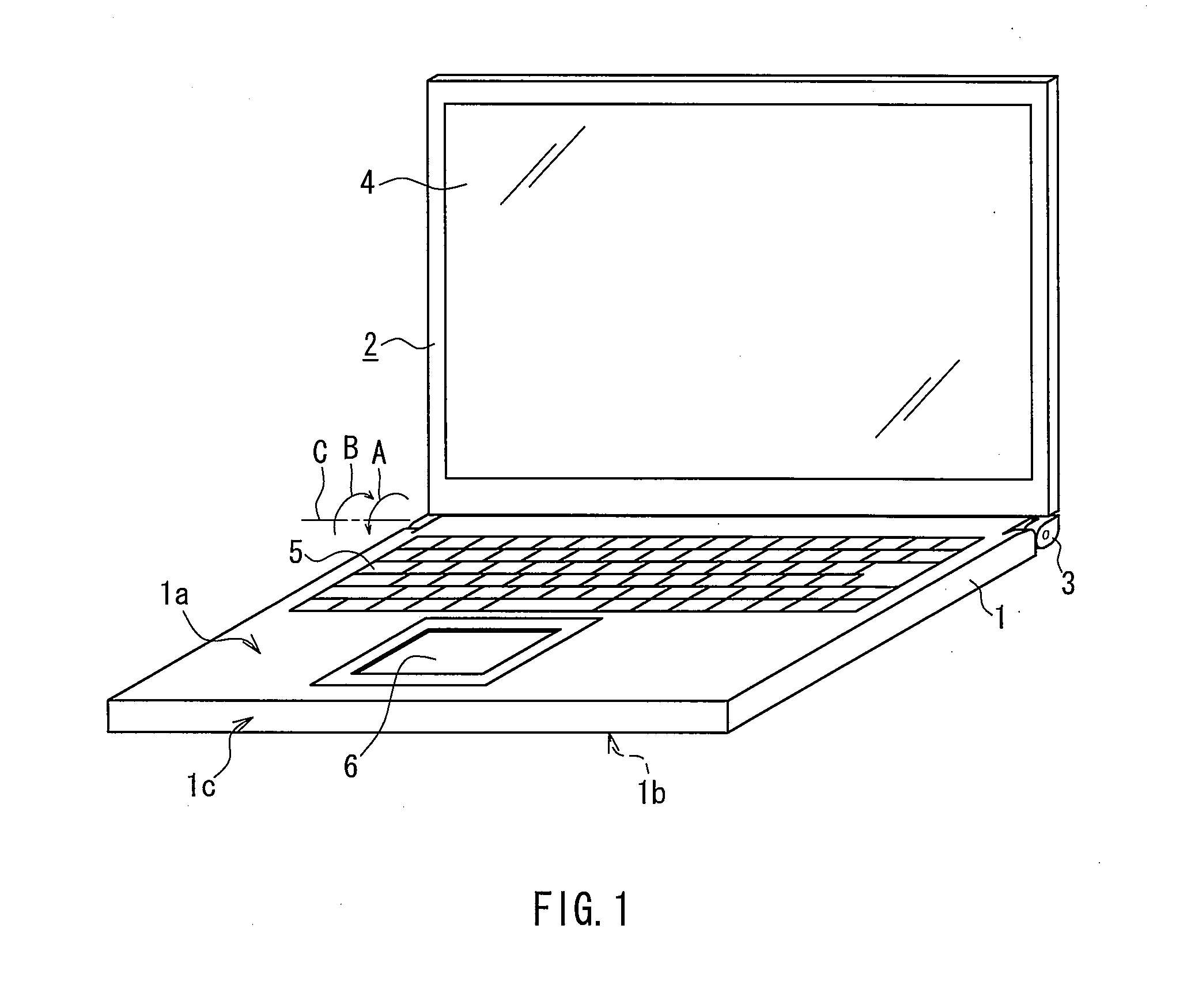
[0033]FIG. 1 is an oblique view illustrating the external appearance of a laptop computer used in this embodiment. Although a laptop computer is used as an exemplary electronic apparatus in the present embodiment, this may be any apparatus that can be used at least on a placement surface such as a tabletop.

[0034]In addition to a laptop computer, the electronic apparatus may be a desktop computer, a display device, a BD (Blu-Ray disc), a video recording and playback apparatus utilizing disc-shaped media, such as a DVD recorder / player, a desktop audio system, and the like.

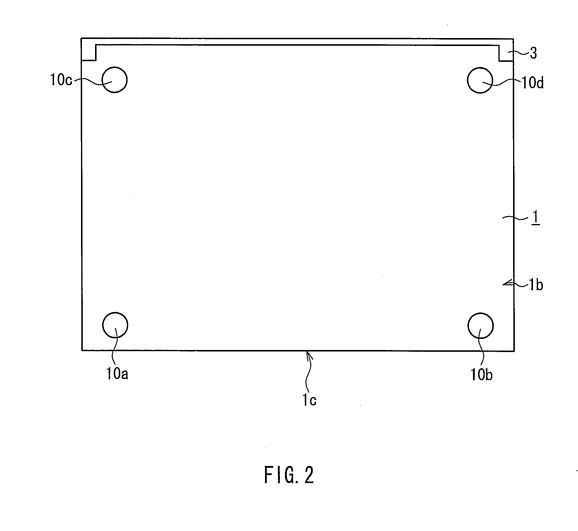
[0035]As shown in FIG. 1, the laptop computer includes a first enclosure 1 and a second enclosure 2. The first enclosure 1 houses a hard disk drive, a circuit board populated with various electrical elements, and the like. The second enclosure 2 includes a display panel 4. For example, the display panel 4 can be implemented as a liquid crystal display panel. The first enclo...

embodiment 2

[0085]Next, a laptop computer provided with a supporting member different from the supporting member described in Embodiment 1 above, namely, a member provided with a foot section equipped with a second orientation adjustment mechanism, will be described as Embodiment 2 below. It should be noted while the configuration of the supporting member of the laptop computer described in Embodiment 2 is different from the laptop computer described in Embodiment 1, it is similar to Embodiment 1 in terms of the configuration of the first enclosure and second enclosure. For this reason, in Embodiment 2, descriptions related to specific exemplary configurations of the first enclosure and second enclosure of the laptop computer are omitted.

5. Configuration of Foot Section Provided with Second Orientation Adjustment Mechanism

[0086]FIG. 7A is a plan view of a foot section 10a equipped with a second orientation adjustment mechanism, as viewed from its lower surface 1b.

[0087]The foot section equippe...


PUM


Abstract

The orientation of an electronic apparatus can be stabilized. At least one foot section among the foot sections provided on a laptop computer is provided with an orientation adjustment mechanism made up of a supporting member, a height adjustment member, and a screw, which makes it possible to eliminate loose play in the first enclosure by adjusting the height of the foot sections to any given height even if loose play occurs in the first enclosure due to disproportions in the height dimensions of the foot sections, deformation etc. of the first enclosure 1, and the like.

Description

BACKGROUND OF THE INVENTION[0001]1. Field of the Invention[0002]The disclosure of the present Application relates to a supporting member supporting an apparatus on a placement surface, as well as to an electronic apparatus equipped with the supporting member.[0003]2. Description of Related Art[0004]An electronic apparatus that can be placed and used on a tabletop, such as a laptop computer or a desktop computer, is often equipped with supporting members, called “rubber feet”, etc. provided on a surface that is brought into resting contact with the tabletop surface serving as a placement surface. The rubber feet, which are often formed from soft rubber, provide cushioning against impacts and vibrations that may be applied to the electronic apparatus. In order to provide efficient cushioning and vibration absorption, the electronic apparatus is often equipped with multiple rubber feet.[0005]However, in recent years, there has been a tendency to make the main body of mobile devices suc...

Claims


Application Information

Patent Timeline
IPC IPC(8): H05K5/02A47B91/00
CPCG06F1/166
Inventor IWAMOTO, AKIRAFURUJIKU, MASARUMATSUYAMA, YOSHINARI
Owner PANASONIC CORP
Learn More