Unlock instant, AI-driven research and patent intelligence for your innovation.

Main and standby link protection method, loop system and apparatus for passive optical network

A passive optical network and main link technology, applied in the field of passive optical network, can solve problems such as link paralysis, single point failure, and network impact, and achieve the effect of reducing impact

Active Publication Date: 2012-07-04
HUAWEI TECH CO LTD
View PDF0 Cites 2 Cited by
  • Summary
  • Abstract
  • Description
  • Claims
  • Application Information

AI Technical Summary

Problems solved by technology

Due to this star structure, the OLT becomes the bottleneck of the PON, and it is prone to single point failure. Once an OLT fails, it will cause the link related to it to be paralyzed, which will have a great impact on the network.

Method used


Image

  • Main and standby link protection method, loop system and apparatus for passive optical network
  • Main and standby link protection method, loop system and apparatus for passive optical network
  • Main and standby link protection method, loop system and apparatus for passive optical network

Examples


Embodiment 1

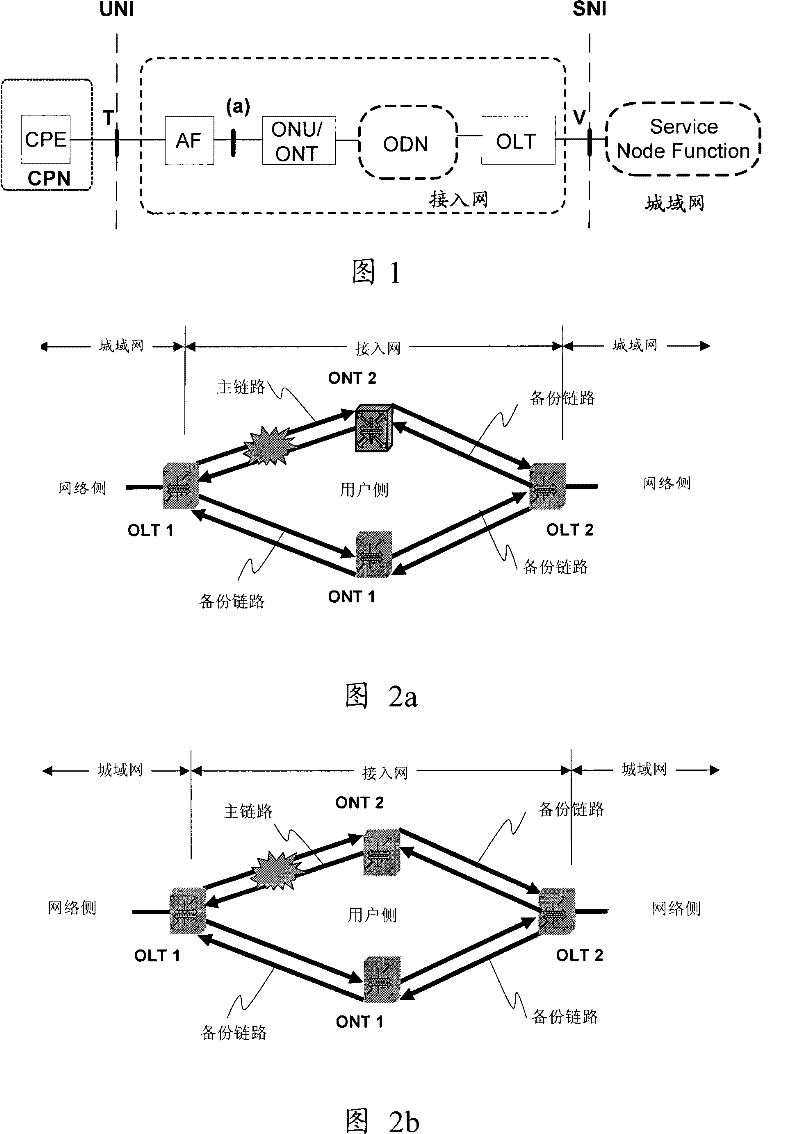
[0032] see Figure 2a , Figure 2a It is a schematic structural diagram a of a PON loop system according to an embodiment of the present invention. In this embodiment, the user-side edge node device is specifically described as an ONT. In other embodiments of the present invention, the user-side edge node device may also be an ONU or a PON extender. In this embodiment, the PON loop system includes OLT1, OLT2, ONT1 and ONT2, wherein, OLT->ONT and ONT->OLT two directions can use a single bidirectional optical fiber, or OLT->ONT direction can use a unidirectional optical fiber, ONT -> Another unidirectional optical fiber is used in the OLT direction. Both ONT1 and ONT2 are connected to OLT1 and OLT2 to form a PON loop. The data flow can flow in both directions, either clockwise OLT1->ONT2->OLT2->ONT1->OLT1 or counterclockwise Flow in the direction of OLT1->ONT1->OLT2->ONT2->OLT1.

[0033] Each PON connection between the PON start node (such as OLT1) and the destination node (...

Embodiment 2

[0039] see image 3 , image 3 It is a schematic structural diagram of a PON loop system according to Embodiment 2 of the present invention. In this embodiment, the PON loop system includes OLT1, OLT2, ONT1, ONT2, ONT3, and ONT4, wherein, the link formed by ONT1 and ONT3, and the link formed by ONT2 and ONT4 are connected to OLT1 and OLT2, thereby forming a PON loop. Similar to Embodiment 1, by establishing a PON loop, an active / standby link or a load sharing link can also be established between any two nodes.

Embodiment 3

[0041] see Figure 4 , Figure 4 It is a schematic structural diagram of a PON loop system according to Embodiment 3 of the present invention. In this embodiment, the PON loop system includes OLT1, OLT2, ONT1, ONT2...ONTn, wherein, ONT1, ONT2...ONTn are all connected to OLT1 and OLT2, thus forming multiple PON rings road. Similar to Embodiment 1, by establishing a PON loop, an active / standby link or a load sharing link can also be established between any two nodes.

[0042] It is easy to understand that the second embodiment above can also be extended in the same manner, and multiple links established by multiple ONTs can be connected to OLT1 and OLT2 at the same time, thereby forming multiple PON loops.


PUM


Abstract

The invention provides a method for protecting a host link and a backup link of a passive optical network (PON). The method comprises the following steps: a PON loop circuit is established, and the PON loop circuit is adopted to configure the host link and a backup link which connect a first node and a second node; when the host link is normal, the first node transmits data by the host link, and the second node receives the data transmitted in the host link; when the host link has failure, the failure is notified to related nodes in the PON loop circuit; the first node transmits data by the backup link, and the second node receives the data transmitted in the backup link. The invention also provides a PON loop circuit system and a border node. The method, the system and the device provided by the invention can reduce influence caused by single link failure on a network in the PON network.

Description

technical field [0001] The invention relates to the field of passive optical network (PON), in particular to a protection method, a loop system and a device for active and standby links of the passive optical network. Background technique [0002] At present, the fiber optic access network (FTTx) mainly adopts the passive optical network (PON, Passive Optical Network) technology. figure 1 It is a schematic structural diagram of an optical access network (OAN) system, which is composed of a customer premises network (CPN, Customer Premises Network), an access network (AN, Access Network) and a service function point (Service Node Function). Among them, in the access network, the Adaptation Function (AF, Adaptation Function) entity is an optional device, which mainly provides the optical network unit (ONU, Optical Network Unit) / optical network terminal (ONT, Optical Network Terminal) interface and user network Interface (UNI, User Network Interface) conversion, AF can also be...

Claims


Application Information

Patent Timeline
Patent Type & Authority Patents(China)
IPC IPC(8): H04Q11/00H04B10/08H04B10/00H04B10/032H04B10/275
CPCH04Q2213/13166H04Q2213/1301H04Q2011/0081H04Q11/0067H04B10/032H04Q2213/13167H04B10/275
Inventor 郑若滨
Owner HUAWEI TECH CO LTD
Features
  • R&D
  • Intellectual Property
  • Life Sciences
  • Materials
  • Tech Scout
  • Unparalleled Data Quality
  • Higher Quality Content
  • 60% Fewer Hallucinations
Learn More