Exoskeleton mechanism based on parallelogram connection-rod and wire rope

A parallelogram, link mechanism technology, applied in manipulators, program-controlled manipulators, motion accessories, etc., can solve problems such as bloated mechanisms, complex control strategies, and the drive device and exoskeleton mechanism are not integrated. The effect of high integration and compact structure

Inactive Publication Date: 2009-06-17
HARBIN INST OF TECH
View PDF0 Cites 25 Cited by
  • Summary
  • Abstract
  • Description
  • Claims
  • Application Information

AI Technical Summary

Problems solved by technology

[0003] The purpose of the present invention is to solve the problem that the existing exoskeleton mechanism used for the hand cannot truly feedback the force received by the end of the robot, and cannot realize two-way active driving. The driving de

Method used


Image

  • Exoskeleton mechanism based on parallelogram connection-rod and wire rope
  • Exoskeleton mechanism based on parallelogram connection-rod and wire rope
  • Exoskeleton mechanism based on parallelogram connection-rod and wire rope

Examples


specific Embodiment approach 1

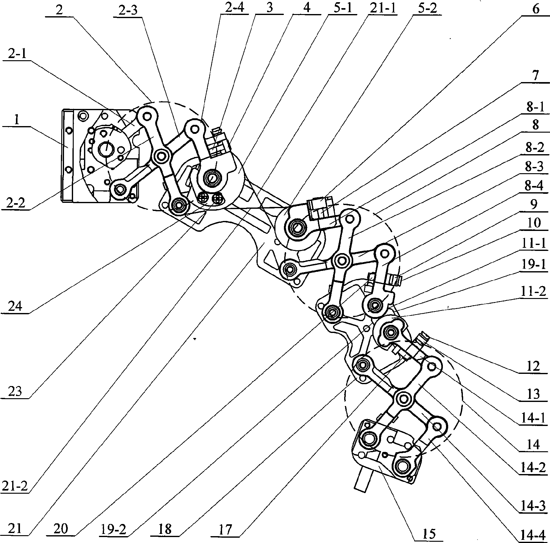
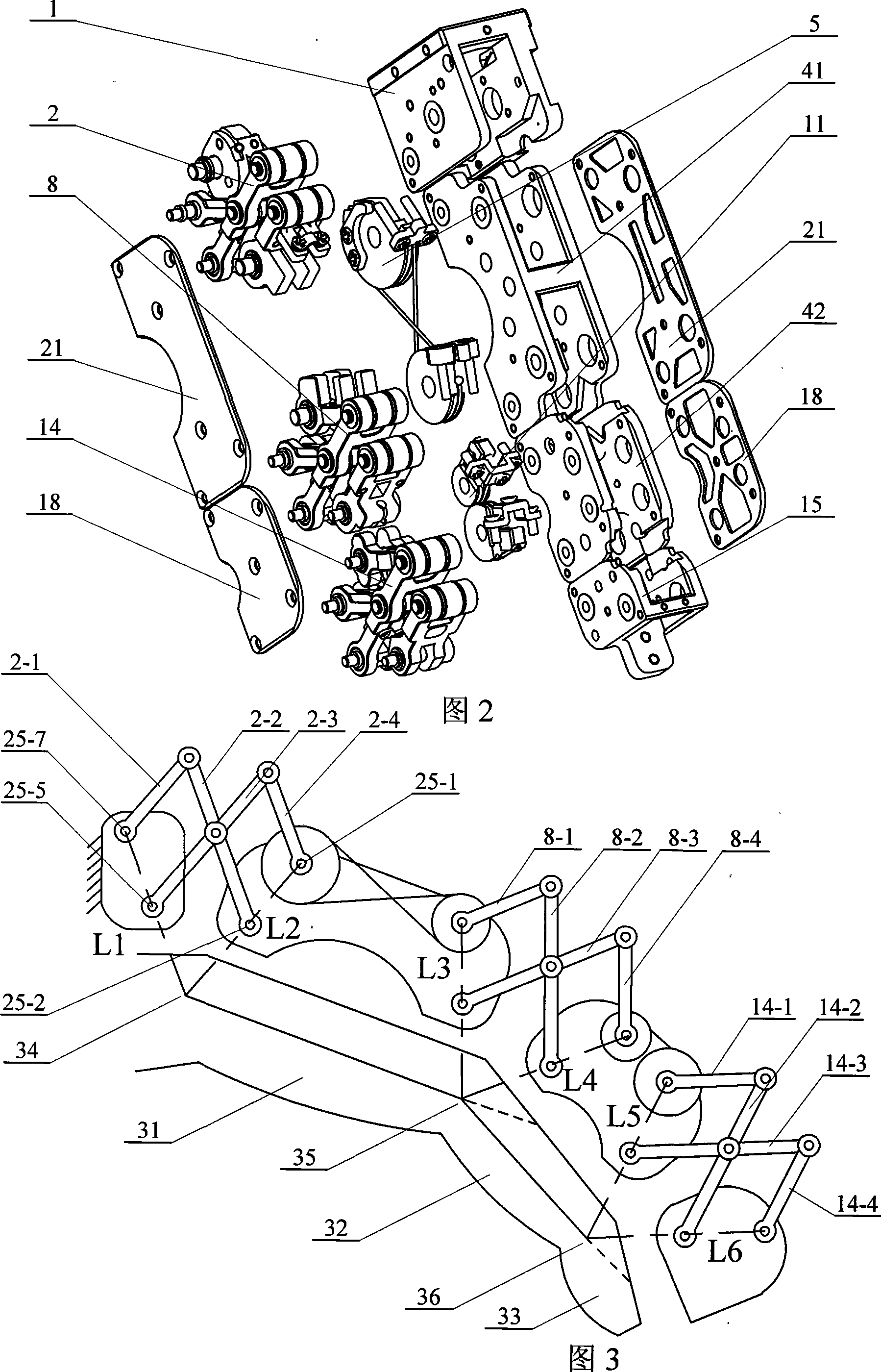
[0006] Specific implementation mode one: (see figure 1 ~ Fig. 4) present embodiment is by the first frame 1, the second frame 41, the 3rd frame 42, two first connecting plates 18, two second connecting plates 21, fingertip interface 15, the first parallel The quadrilateral linkage mechanism 2, the second parallelogram linkage mechanism 8, the third parallelogram linkage mechanism 14, the first wire rope transmission mechanism 5, and the second wire rope transmission mechanism 11 are composed of two first connecting plates 18 respectively arranged on the second wire rope transmission mechanism. On both sides of the three frame 42, two second connecting plates 21 are respectively arranged on both sides of the second frame 41, and the first parallelogram linkage mechanism 2 is composed of the first connecting rod 2-1, the second Connecting rod 2-2, the 3rd connecting rod 2-3 and the 4th connecting rod 2-4 form, and the second parallelogram linkage mechanism 8 is made up of No. 1 ...

specific Embodiment approach 2

[0008] Specific implementation mode two: (see figure 1 ~ FIG. 4 ) The transmission ratio of the first wire rope transmission mechanism 5 in this embodiment is 1:1.4, and the transmission ratio of the second wire rope transmission mechanism 11 is 1.4:1. Others are the same as in the first embodiment.

specific Embodiment approach 3

[0009] Specific implementation mode three: (see figure 1 ~ Fig. 4) The first frame 1, the second frame 41, the third frame 42, the two first connecting plates 18, the two second connecting plates 21, the fingertip interface 15, the first The materials of the parallelogram linkage 2 , the second parallelogram linkage 8 and the third parallelogram linkage 14 are all LC4. Others are the same as in the first embodiment.


PUM


Abstract

The present invention relates to an external skeleton mechanism based on parallelogram connecting rod and wire cable, and relates to an external skeleton mechanism. The aim of the invention is to settle the problems that the existing external skeleton mechanism which is used aiming at the hand part can not realize bidirectional active driving, the mechanism is overstaffed, the strong friction between the cable and the mechanism makes the control more difficult, etc. A first thread wheel and a second thread wheel of the invention are respectively installed on two sides of the upper part of second machine frame. The first thread wheel is coaxial with one end of the fourth connecting rod. The second thread wheel is coaxial with one end of Number1 connecting rod. One end of the second wire cable is connected with a clamp plate. The other end of the second wire cable is installed on a second adjusting slider. The third thread wheel and the fourth thread wheel are respectively installed on two sides of the upper part of third machine frame. The third wire wheel is coaxial with the Number4 connecting rod. The fourth thread wheel is coaxial with connecting rod 4. Each joint of the invention adopts a parallelogram link mechanism. The middle driving component adopts a wire cable for transmission. The hand can be surrounded with the external skeleton form for executing an enveloping movement.

Description

technical field [0001] The invention relates to an exoskeleton mechanism. Background technique [0002] At present, the most typical exoskeleton mechanisms in the world are: EXOS exoskeleton hand, CyberGrasp (force feedback) data glove. The design ideas of these exoskeleton mechanisms mainly use the knuckles of human fingers as part of their exoskeleton mechanisms, so this exoskeleton mechanism is not an independent exoskeleton mechanism, that is, without the cooperation of human fingers, this exoskeleton mechanism Mechanisms cannot generate any movement. Therefore, it will inevitably bring the following three problems: ① It needs to cooperate with each knuckle of the human hand to form a polygonal mechanism to generate motion, which will affect the reality of force perception during force feedback. ②Both cannot realize two-way active driving, which can only make the human hand produce stretching motion and the motion originates from the human hand. ③Using rope transmissi...

Claims


Application Information

Patent Timeline
IPC IPC(8): A61H1/00A63B23/16B25J13/00B25J9/16
Inventor 谢宗武方红根刘宏王书付孙奎倪风雷赵京东
Owner HARBIN INST OF TECH
Why Eureka
Try Eureka