Installation structure for roof rail

A structure and edge beam technology, applied in the field of installation structure of the upper edge beam, can solve the problems of difficulty in ensuring water tightness, enlargement, rainwater intrusion, etc., and achieve the effect of preventing rainwater from immersing in the car

Active Publication Date: 2009-06-17
FALTEC CO LTD
View PDF3 Cites 4 Cited by
  • Summary
  • Abstract
  • Description
  • Claims
  • Application Information

AI Technical Summary

Problems solved by technology

[0007] However, when the distance between the roof and the vehicle inner panel is not uniform, it is difficult to ensure the watertightness of the hole formed in the roof
There is a problem that rainwater infiltrates into the car through the hole, reducing the value of the product
In addition, when a load is added to the roof rail, the positional relationship between the roof rail and the hole formed in the roof will change, so there is a problem that the possibility of rainwater intrusion increases.

Method used


Image

  • Installation structure for roof rail
  • Installation structure for roof rail
  • Installation structure for roof rail

Examples


Embodiment Construction

[0027] Hereinafter, embodiments of the roof rail mounting structure of the present invention will be described with reference to the drawings.

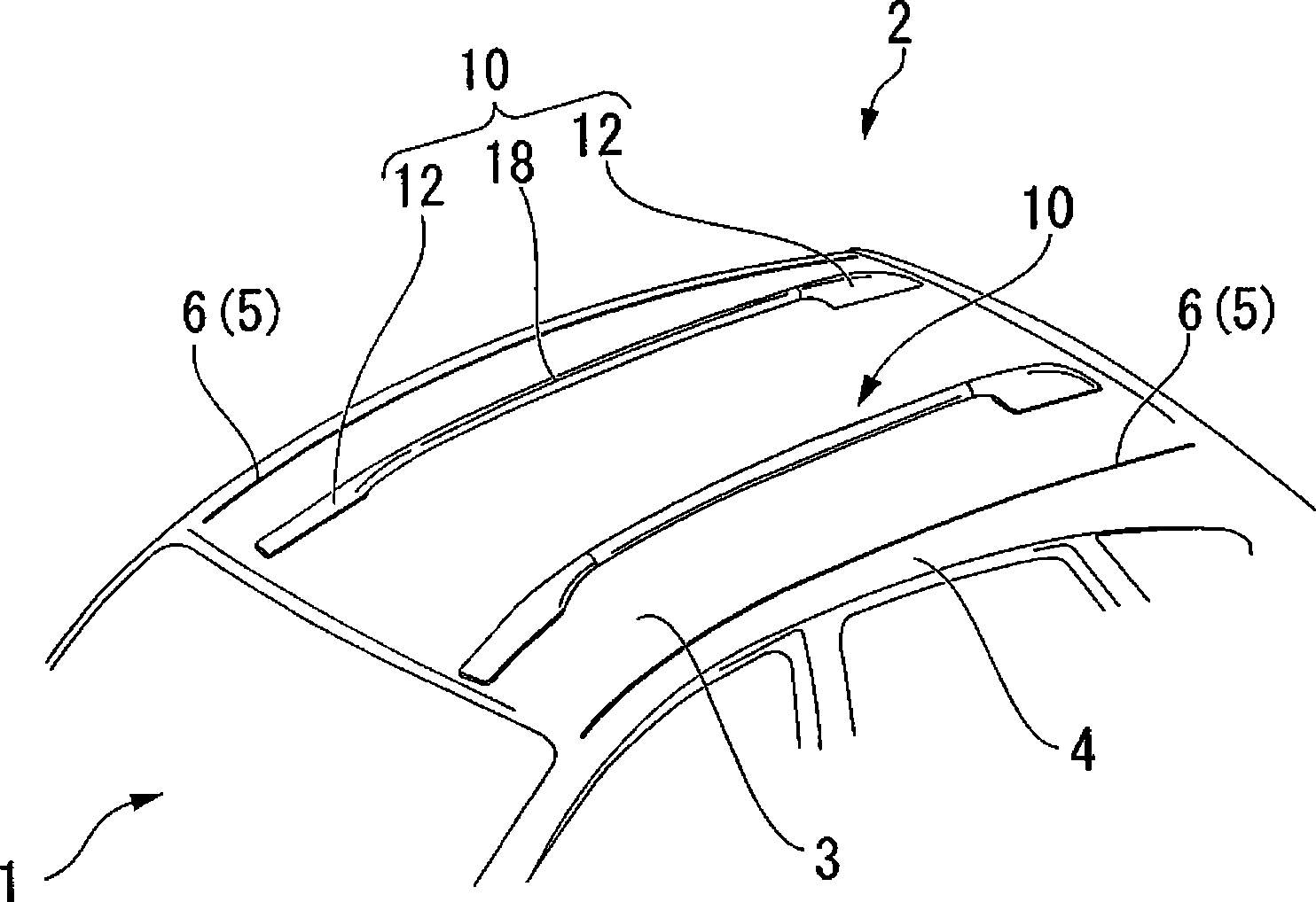
[0028] figure 1 It is an external perspective view showing the mounting structure of the roof side rail according to the embodiment of the present invention.

[0029] On the roof 2 of a vehicle 1 such as a passenger car, a pair of roof side rails 10 are provided on both end sides thereof along the front-rear direction of the vehicle 1 .

[0030] Each roof side rail 10 is constituted by a pair of leg parts 12 closely arranged on the ceiling 2 and a rail part 18 arranged between the pair of leg parts 12 .

[0031] Furthermore, each roof side rail 10 is arranged on the vehicle inner side than the pair of roof moldings 6 provided on the roof 2 . That is, the roof molding 6 is fitted into the joining portion 5 between the roof cover 3 and the vehicle body side panel 4 . Each roof side rail 10 is arranged on the inner side of the vehicl...


PUM


Abstract

The installation structure of a roof rail in which the roof rail is attached to a vehicle inner panel provided underneath a roof panel, through a hole part provided in a roof panel, the installation structure includes: a protruding part which is provided protruding downward from a lower surface of the roof rail, is inserted into the hole part with a gap in-between, and is attached to an upper surface of the vehicle inner panel; and a watertight part which encloses the protruding part, and is flattened between the lower surface of the roof rail and the upper surface of the roof panel, wherein a part of the watertight part extends through the hole part and protrudes beyond the lower surface of the roof panel.

Description

technical field [0001] The present invention relates to a mounting structure of a roof rail of a vehicle. Background technique [0002] The contents of Japanese Patent Application No. 2007-319825 with a filing date of December 11, 2007 from which priority is claimed are incorporated herein by reference. [0003] On both sides of the width direction of the roof of the vehicle, such as Figure 5 As shown, there may be a pair of roof side rails 101 provided for loading luggage or the like. Such as Figure 6A , Figure 6B As shown, a structure in which the roof side sill 101 is fastened and fixed with bolts is generally adopted at a portion where the strength of the joint portion between the roof panel 104 and the body side panel 105 is ensured. [0004] For example, in Japanese Patent Application Laid-Open No. 09-095185, a roof side rail is attached at a position away from the junction of the roof and the side panel of the vehicle body. A reinforcing element is provided at ...

Claims


Application Information

Patent Timeline
Patent Type & Authority Applications(China)
IPC IPC(8): B60R9/04
CPCB60R9/04B60R13/025B62D25/06
Inventor 清田直彦
Owner FALTEC CO LTD
Why Eureka
Try Eureka