Underwater local dry-method GMAW welding torch for double-layer gas structure

A local dry method and structural water technology, applied in the characteristics of welding electrodes, welding equipment, welding accessories, etc., can solve the problems of easy turbulent flow, unsatisfactory drainage effect, large gas flow, etc., and achieve the effect of improving dryness.

Inactive Publication Date: 2019-01-29
JIANGSU MARITIME INST
View PDF1 Cites 5 Cited by
  • Summary
  • Abstract
  • Description
  • Claims
  • Application Information

AI Technical Summary

Problems solved by technology

However, due to the existence of gas inside the torch as both shielding gas and drain gas, the flow rate of drain gas cannot be adjusted independently
When welding in large water depth, if the flow rate of welding shielding gas is large and it is a rotating air flow, the gas flow rate in the welding torch is too large, and it is prone to turbulent flow, which will easily cause instability to the welding arc
In addition, the drainage gas used in this device is normal temperature gas, which is not ideal for the drainage of water splashed on the surface of the weld during the drainage process.

Method used


Image

  • Underwater local dry-method GMAW welding torch for double-layer gas structure
  • Underwater local dry-method GMAW welding torch for double-layer gas structure
  • Underwater local dry-method GMAW welding torch for double-layer gas structure

Examples


Embodiment Construction

[0027] The present invention will be specifically described below in conjunction with the accompanying drawings.

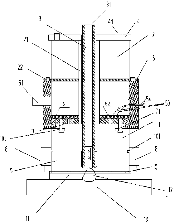
[0028] as attached figure 1 As shown, a double-layer gas structure underwater partial dry GMAW welding torch includes a drainage cover 1 that can rotate and a DC motor 2 that drives the rotation of the drainage cover. The upper end of the DC motor 2 uses top plate bolts 41 and top plate 4 Connect, and the lower end utilizes motor bolt 22 and drain static air cover 5 to connect. The drainage cover 1 is provided with four drainage gas outlet holes 101 in the circumferential direction, which are specially used to discharge the gas in the welding torch out of the welding torch through the outlet holes. The inside of the motor shaft of the DC motor 2 is processed with a large-diameter through hole to form a hollow shaft 21 for passing through the welding torch 3 of the special extended nozzle. The upper end of the welding torch of the extended nozzle is provided with ...


PUM


Abstract

The invention specifically relates to an underwater local dry-method GMAW welding torch for a double-layer gas structure. The underwater local dry-method GMAW welding torch for the double-layer gas structure comprises a direct-current motor, a welding gun with an extended nozzle, a water drainage cover, and a water drainage gas-settling cover installed between the direct-current motor and the water drainage cover, wherein a hollow shaft of the direct-current motor extends downwards and penetrates through a hollow part of the water drainage gas-settling cover to reach the bottom surface of thewater drainage gas-settling cover; the water drainage gas-settling cover is fixedly installed on the lower surface of the direct-current motor; water drainage gas is charged into an inner chamber of the water drainage gas-settling cover through an intake port formed in the sidewall of the water drainage gas-settling cover; an annular rotary ventilation disc is installed on the bottom surface of the water drainage gas-settling cover, the upper surface of the water drainage cover is fixedly connected to the lower surface of the rotary ventilation disc, and a through hole adaptive to the rotary ventilation disc is formed in the upper surface of the water drainage cover and used for realizing flowing of the gas; an exhaust hole is formed in the sidewall of the water drainage cover and rotary blades are arranged on the sidewall of the water drainage cover; the water drainage cover can be driven to rotate through the rotation of the direct-current motor, the rotary blades can be driven to rotate, so that the water drainage effect is improved; and the welding gun with the extended nozzle passes through the hollow shaft and then penetrates out of the water drainage cover. According to thedevice, the adopted water drainage gas is high-temperature gas, and a great water drainage effect is achieved.

Description

technical field [0001] The invention relates to the field of underwater partial dry gas shielded welding, in particular to an underwater local dry GMAW welding torch with a double-layer gas structure. Background technique [0002] Underwater partial dry gas shielded welding is currently an underwater welding method that is a research hotspot. This method is an automatic or semi-automatic welding method that uses protective gas sprayed from a specific drainage cover to make a local dry environment in the weld area within a certain range, thereby ensuring the welding quality. [0003] In the prior art, the application number is 20171000477917, and the name of the invention is: double air flow structure local dry method underwater robot welding miniature drainage cover. Although the disclosed device realizes the effect of gas rotation and drainage, the speed of gas rotation is limited by the mechanical structure , can’t be adjusted, and the device simply utilizes gas to drain ...

Claims


Application Information

Patent Timeline
Patent Type & Authority Applications(China)
IPC IPC(8): B23K9/28B23K9/16B23K9/32
CPCB23K9/16B23K9/28B23K9/326
Inventor 朱征宇张强勇刘桂香赵先锐陈勇周建桃张通超马春卉王杰顾凡
Owner JIANGSU MARITIME INST
Why Eureka
Try Eureka