Water stop structure of movable working gate and sealing device

A sealing device and water-stop technology, applied in water conservancy projects, marine engineering, coastline protection and other directions, can solve problems such as uneven gate gaps, and achieve the effects of convenient project implementation, reduced capacity, and improved adaptability

Active Publication Date: 2014-12-17
CHINA GEZHOUBA GROUP MACHINERY & SHIP
View PDF7 Cites 5 Cited by
  • Summary
  • Abstract
  • Description
  • Claims
  • Application Information

AI Technical Summary

Problems solved by technology

[0007] The technical problem to be solved by the present invention is to provide a water-stop structure and sealing device for the movable working door of the lower gate of a large ship lift, which can realize the sealing of the surface hole gate with only three water-stop dual surfaces, and can effectively solve the problem of gate The problem of uneven clearance is especially suitable for the moving work door of the lower lock head of large ship lifts

Method used


Image

  • Water stop structure of movable working gate and sealing device
  • Water stop structure of movable working gate and sealing device
  • Water stop structure of movable working gate and sealing device

Examples


Embodiment 1

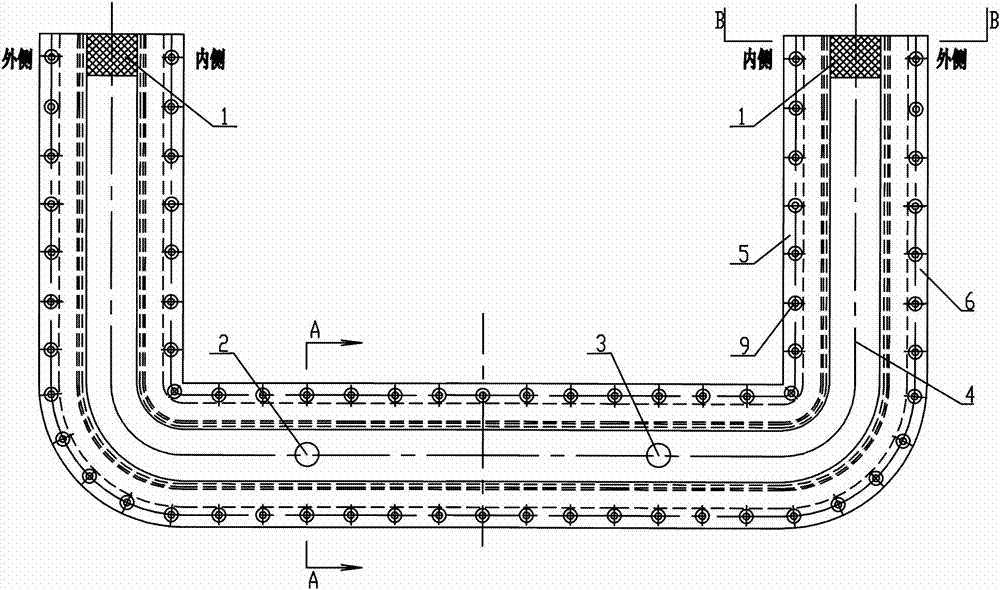
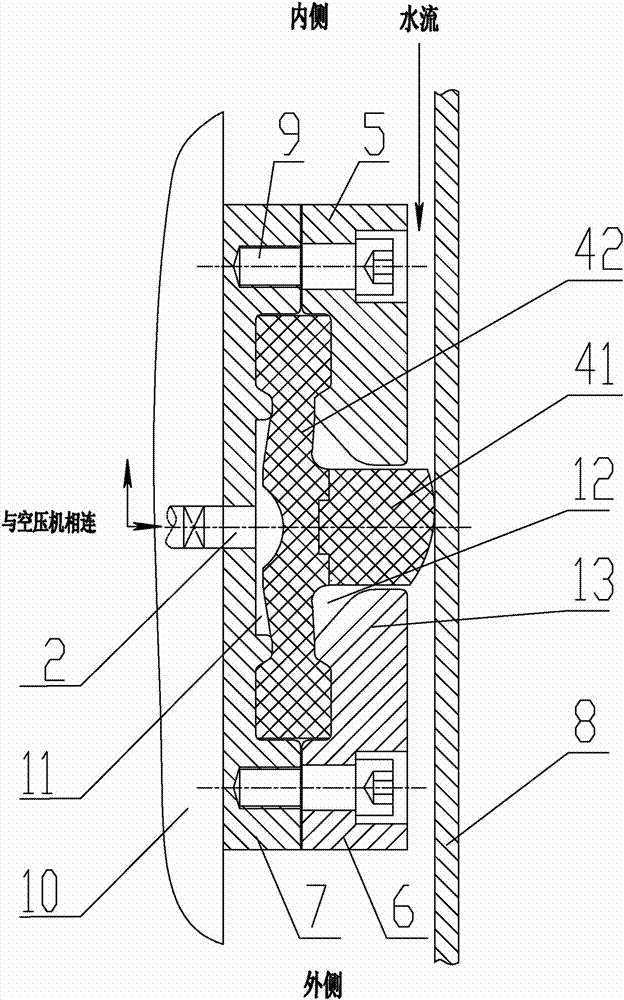
[0034] like Figure 1~3 Among them, a water-stop structure for a mobile working gate, the water-stop structure is in the shape of a "U", cavity plugs 1 are provided at both ends of the "U", the seat plate 7 is connected with the gate panel 10, and the sealing device 4 fixedly installed on the seat plate 7 through the inner pressure plate 5 and the outer pressure plate 6;

[0035] In the sealing device 4, a pressure chamber 11 is formed between the air seal member 42 and the seat plate 7, and the seat plate 7 is provided with an air inlet 2 and an air outlet 3 communicating with the pressure chamber 11. In the sealing device 4, there is also There is a water seal head 41 which is driven by the air seal 42 to contact or separate from the water-stop dual surface 8 of the door slot;

[0036] Preferably, at the position of the cavity plug 1, the bottom of the water seal head 41 is straight and in direct contact with the seat plate 7, and the two sides of the cavity plug 1 are prov...

Embodiment 2

[0044] Such as Figure 2~4 Among them, a sealing device, the sealing device is fixedly installed on the seat plate 7 through the inner pressure plate 5 and the outer pressure plate 6, the two ends of the sealing device are provided with cavity plugs 1, and the air seal 42 in the sealing device 4 is connected to the seat plate A pressure chamber 11 is formed between the 7, and the seat plate 7 is provided with an air inlet 2 and an air outlet 3 communicating with the pressure chamber 11, and the sealing device 4 is also provided with a dual surface driven by the air seal 42 and the water-proof surface of the door groove. 8 contact or separate water seal head 41;

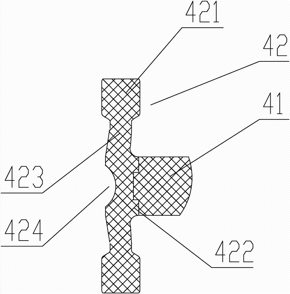
[0045] The air seal 42 is movably engaged with the water seal 41 , wherein the hardness of the air seal 42 is lower than that of the water seal 41 .

[0046] The air seal 42 is provided with a connection portion 422 for connecting with the water seal head 41, and both sides of the air seal 42 are connected to the win...


PUM


Abstract

The invention discloses a water stop structure of a movable working gate and a sealing device. The water stop structure comprises a U-shaped body, wherein cavity plugs are arranged at two ends of the U-shaped body; a seat plate is connected with a gate panel; the sealing device is fixedly mounted on the seat plate through an inner pressing plate and an outer pressing plate; a pressurizing chamber is formed between an air seal piece in the sealing device and the seat plate; an air inlet hole and an air outlet hole communicated with the pressurizing chamber are formed in the seat plate; a water seal head which comes into contact with or is separated from a gate groove water stop dual-face under the driving of the air seal piece is further arranged in the sealing device; the air inlet hole is connected with an air compressor. Compared with the prior art, the water stop structure of the movable working gate and the sealing device have the beneficial effects that a water seal device is used in a U-shaped form so as to be applicable to a surface-hole gate having only three water stop dual-faces (namely the dual-face is not arranged in the horizontal direction on the gate). Due to the adoption of a split sealing device structure and due to the hardness difference, the technical problem that a pressurized type water seal is likely to damage in the prior art is solved.

Description

technical field [0001] The invention relates to the field of water-stopping and leak-stopping in the gaps around the surface gates of water conservancy and hydropower projects, in particular to a water-stopping structure and a sealing device for a mobile working gate. Background technique [0002] In water conservancy and hydropower projects, water leakage at the gate not only causes unnecessary loss of water resources, but also affects the working environment of the gate, and even causes cavitation of buildings and vibration of the gate, threatening the safety of the project, so water-stop devices must be installed around the gate . At present, most of the surface hole gates use pre-pressed rubber water-stop devices, but the pre-pressed rubber water-stop devices have poor adaptability to the gate gap, local water leakage, and fast wear of the water-sealing rubber when the door is moved. Large closing force and other shortcomings. [0003] In order to adapt to changes in t...

Claims


Application Information

Patent Timeline
Patent Type & Authority Applications(China)
IPC IPC(8): E02B7/54
Inventor 温焕翃韩烈彪熊雄练柳君刘礼华于庆奎
Owner CHINA GEZHOUBA GROUP MACHINERY & SHIP
Why Eureka
Try Eureka