Landing buffer leg structure

A buffer mechanism and leg technology, which is applied in the field of space exploration, can solve the problems that the lander does not have the ability to move and the legs do not have the ability to repeatedly land, and achieves the effect of solving repeated landings and movements and significant economic value.

Pending Publication Date: 2021-06-01
SHANGHAI PLATFORM FOR SMART MFG CO LTD
View PDF0 Cites 1 Cited by
  • Summary
  • Abstract
  • Description
  • Claims
  • Application Information

AI Technical Summary

Problems solved by technology

At present, the aluminum honeycomb leg structure has the following limitations: on the one hand, the irreversible compression of the aluminum honeycomb leg structure after landing makes the legs unable to repeatedly land; on the other hand, the position of the legs is locked after landing, and the lander does not have the ability to move

Method used


Image

  • Landing buffer leg structure
  • Landing buffer leg structure
  • Landing buffer leg structure

Examples


Embodiment Construction

[0027] The following will clearly and completely describe the technical solutions in the embodiments of the application with reference to the drawings in the embodiments of the application. Apparently, the described embodiments are only some of the embodiments of the application, not all of them. Based on the embodiments in this application, all other embodiments obtained by persons of ordinary skill in the art without making creative efforts belong to the scope of protection of this application.

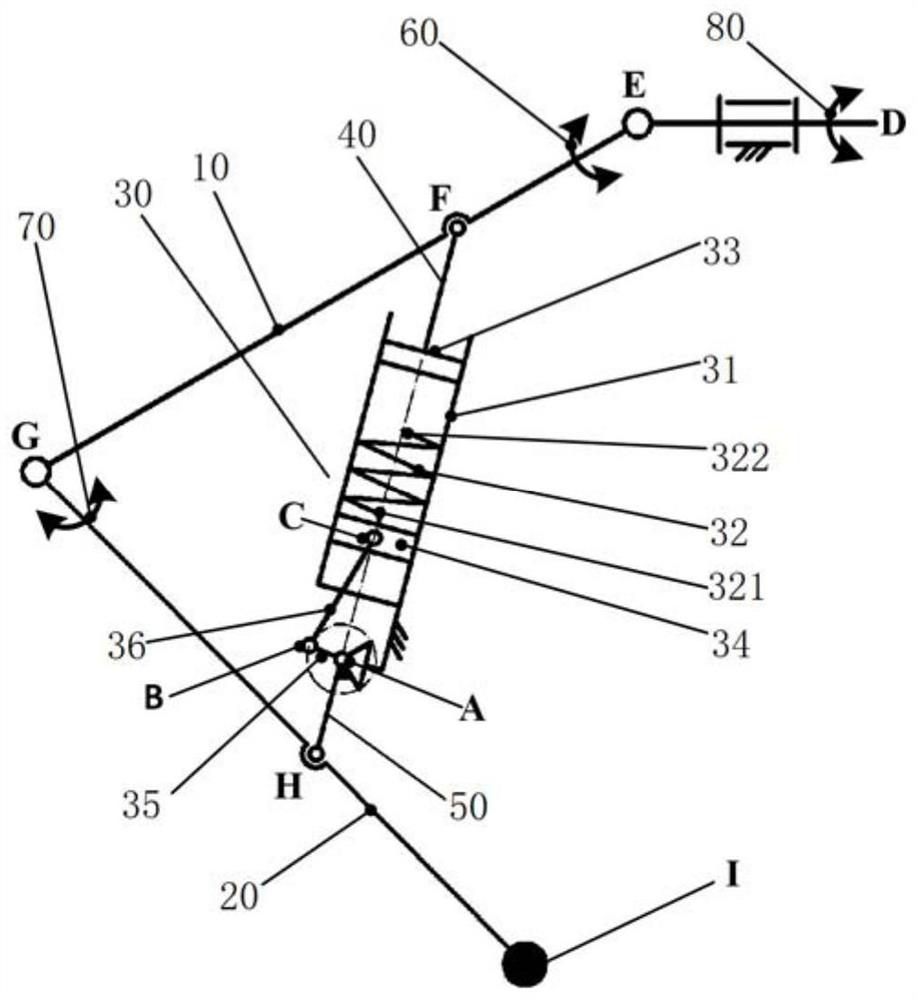
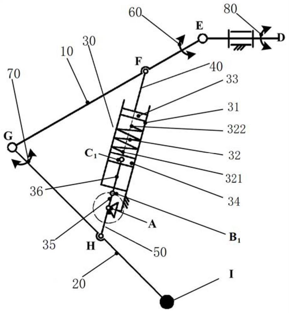
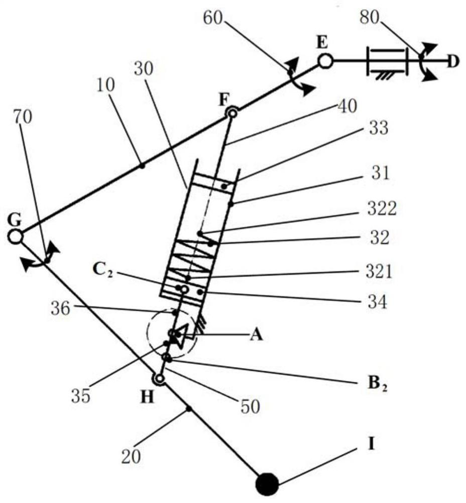
[0028] Such as Figure 1 to Figure 3 As shown, in one embodiment of the present application, a landing buffer leg structure includes: a thigh portion 10, a lower leg portion 20 and a buffer mechanism 30, wherein the thigh portion 10 and the lower leg portion 20 is rotatably connected, the first end of the buffer mechanism 30 is rotatably connected to the thigh 10 , and the second end of the buffer mechanism 30 is rotatably connected to the lower leg 20 . By setting the buffer mecha...


PUM


Abstract

The invention discloses a landing buffer leg structure which comprises a thigh part, a shank part and a buffer mechanism, wherein the thigh part is rotationally connected with the shank part, the first end of the buffer mechanism is rotationally connected with the thigh part, and the second end of the buffer mechanism is rotationally connected with the shank part. By arranging the buffer mechanism, the buffer landing and moving functions are integrated, and the technical problems of repeated landing and moving can be solved; the landing buffer leg structure can be switched into a buffer action mode when landing, the passive buffer capacity is provided for the legs under the action of the buffer mechanism, so that the peak value of impact loads borne by the driving mechanisms on the legs is weakened; and the landing buffer leg structure is switched to a sleep mode when walking, the buffer mechanism does not work and enters the sleep mode, and the dynamic response capability of the legs can be improved.

Description

technical field [0001] The application belongs to the field of space detection technology, and in particular relates to a landing buffer leg structure. Background technique [0002] Aluminum honeycomb buffers or hydraulic buffers are often used in the legs of legged landers used in current space exploration to absorb the impact energy during landing. When the aluminum honeycomb legs land, the irreversible deformation of the aluminum honeycomb is used to absorb energy. The hydraulic buffer legs use the internal damping holes to generate damping force buffering. Due to the sealing and temperature control problems of the hydraulic system, the existing legged landers mostly use the aluminum honeycomb leg structure. . At present, the aluminum honeycomb leg structure has the following limitations: on the one hand, the irreversible compression of the aluminum honeycomb leg structure after landing makes the legs unable to repeatedly land; on the other hand, the position of the legs...

Claims


Application Information

Patent Timeline
IPC IPC(8): B64G1/16B62D57/032F16F15/067
CPCB64G1/16B62D57/032F16F15/067
Inventor 孙竞陈先宝刘仁强高峰尹科
Owner SHANGHAI PLATFORM FOR SMART MFG CO LTD
Why Eureka
Try Eureka