Automatic polishing and derusting system for two sides of U-shaped rib

An automatic, U-shaped technology, used in abrasives, abrasive jet machine tools, used abrasive processing devices, etc., can solve the problems of inability to realize automatic feeding and unloading, occupying workshop operating space, and inability to remove U-rib corrosion. , to achieve the effect of reliable support, reduction of production and processing costs, and high degree of automation

Active Publication Date: 2022-07-29
CHINA RAILWAY SHANQIAO GRP CO LTD
View PDF12 Cites 0 Cited by
  • Summary
  • Abstract
  • Description
  • Claims
  • Application Information

AI Technical Summary

Problems solved by technology

[0002] At present, the method of derusting the position to be welded of the U-rib generally adopts the laser derusting method. During the derusting operation of the U-rib laser derusting device, the laser derusting device is installed at a fixed position. The two ends of the device are arranged to convey the U-ribbed conveying roller table. The length of each conveying roller table is basically the same as the length of the U-ribbed. Usually, the U-rib needs to be moved by the conveying roller table so that the laser derusting device can take all the U-ribbed parts. The welding parts have been polished and derusted. With this processing method, not only is the work efficiency low, it is difficult to ensure that the primer and floating rust on each part of the U rib can be removed by grinding, and it is impossible to remove the burr on the edge of the U rib and the rust on the burr position. The operation effect is often not ideal, and manual secondary operations are required; in addition, the length of the U-rib is generally long, and the maximum length can reach 20 meters. Using the above-mentioned method to process will occupy a large amount of operating space in the workshop, and it is impossible to realize automation. material, blanking

Method used


Image

  • Automatic polishing and derusting system for two sides of U-shaped rib
  • Automatic polishing and derusting system for two sides of U-shaped rib
  • Automatic polishing and derusting system for two sides of U-shaped rib

Examples


Embodiment Construction

[0073] The technical solutions in the embodiments of the present invention will be clearly and completely described below with reference to the accompanying drawings in the embodiments of the present invention. Obviously, the described embodiments are only a part of the embodiments of the present invention, but not all of the embodiments. Based on the embodiments of the present invention, all other embodiments obtained by those of ordinary skill in the art without creative efforts shall fall within the protection scope of the present invention.

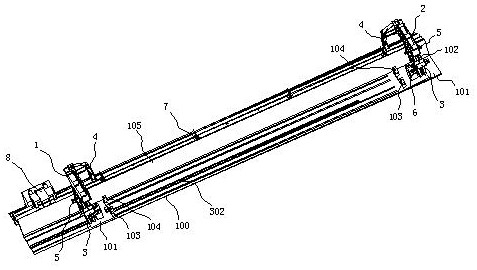
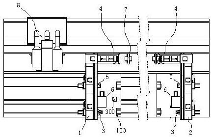
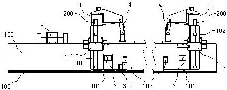
[0074] see Figures 1 to 25 , a U-rib bilateral automatic grinding and derusting system, including:

[0075] The bottom processing base 100 has a placement area and a rust removal processing area. The placement area is divided into a loading area and a blanking area. The placement area of ​​the bottom processing base 100 is installed with a movable frame 1 and a fixed frame 2. The movable frame 1 and the fixed frame The structure of ...


PUM


Abstract

The invention discloses a U-rib double-side automatic polishing and derusting system which comprises a bottom machining base provided with a containing area and a derusting machining area, the containing area is divided into a feeding area and a discharging area, and the containing area of the bottom machining base is provided with a movable rack and a fixed rack; the movable rack and the fixed rack are each provided with a bottom rack base, a feeding stand column, a discharging stand column and a top cross beam frame, and the top cross beam frames are fixedly installed on the tops of the feeding stand columns and the tops of the discharging stand columns. A feeding placing seat corresponding to the feeding area and a discharging placing seat corresponding to the discharging area are further fixedly mounted on the bottom rack seat; the device further comprises a feeding mechanism, a discharging mechanism, a sand blasting and rust removing mechanism, a heavy hammer swing type carrier roller and a transferring and clamping mechanism. The device is high in automation degree, can automatically complete the whole process of feeding, sand blasting and rust removing operation and discharging of a single U-shaped rib, basically does not need manual intervention, well reduces the labor cost, improves the production efficiency, and is small in space occupation of the whole system equipment.

Description

technical field [0001] The invention relates to the technical field of U-shaped rib rust removal, in particular to a U-rib bilateral automatic grinding and rust removal system. Background technique [0002] At present, the method of removing rust on the to-be-welded position of the U-rib generally adopts the laser descaling method. The two ends of the device are arranged with conveying rollers for conveying U-ribs. The length of each conveying roller is basically the same as the length of the U-rib. Usually, the U-rib needs to be moved by the conveying rollers, so that the laser rust removal device can remove all the U-ribs. The welding parts are all polished and derusted. Using this processing method not only has low work efficiency, but also it is difficult to ensure that the primer and rust on each part of the U-rib can be polished and removed, and the edge burrs of the U-rib and the rust at the burr position cannot be removed. The operation effect is often unsatisfactor...

Claims


Application Information

Patent Timeline
Patent Type & Authority Applications(China)
IPC IPC(8): B24C1/08B24C3/06B24C5/04B24C9/00B65G47/90
CPCB24C1/086B24C3/06B24C5/04B24C9/00B65G47/905B65G47/901
Inventor 邢扬杨翠屏杨金山柴飞胡广瑞龙东利陈敏刘申刘昊陈彤
Owner CHINA RAILWAY SHANQIAO GRP CO LTD
Why Eureka
Try Eureka