Laser flare measuring device and measuring method thereof

A technology of laser spot and measuring device, which is applied in the direction of measuring device, optical device, and completely visual method, which can solve the problems of laser beam drift, affecting the authenticity and correctness of spot measurement, and achieve the effect of accurate beam quality

Inactive Publication Date: 2009-06-17
SUZHOU UNIV
View PDF0 Cites 100 Cited by
  • Summary
  • Abstract
  • Description
  • Claims
  • Application Information

AI Technical Summary

Benefits of technology

This technology uses an optical system called this inventor's micromirre mirror (MOM) array that allows for precise adjustment over different angles during operation without affecting how well they work at all times. It can detect both linearly polarized or circularly polarizing beams simultaneously while also measuring their size distribution. By doing these measurements on multiple images taken from one same location, we get better understanding about the properties of the lens used by the MONOX machine compared to traditional methods like film cameras.

Problems solved by technology

This patents discusses methods for accurately determining the size (or radius) of a specific part called a "beam". These techniques involve scanning a special kind of laster along one axis while maintaining focusability over another plane. They aim towards improving accuracy and efficiency in detecting small objects like puls marks from laser sources. Additionally, they provide technical means for studying laser radiation patterns and their impact on measurements.

Method used


Image

  • Laser flare measuring device and measuring method thereof

Examples


Embodiment 1

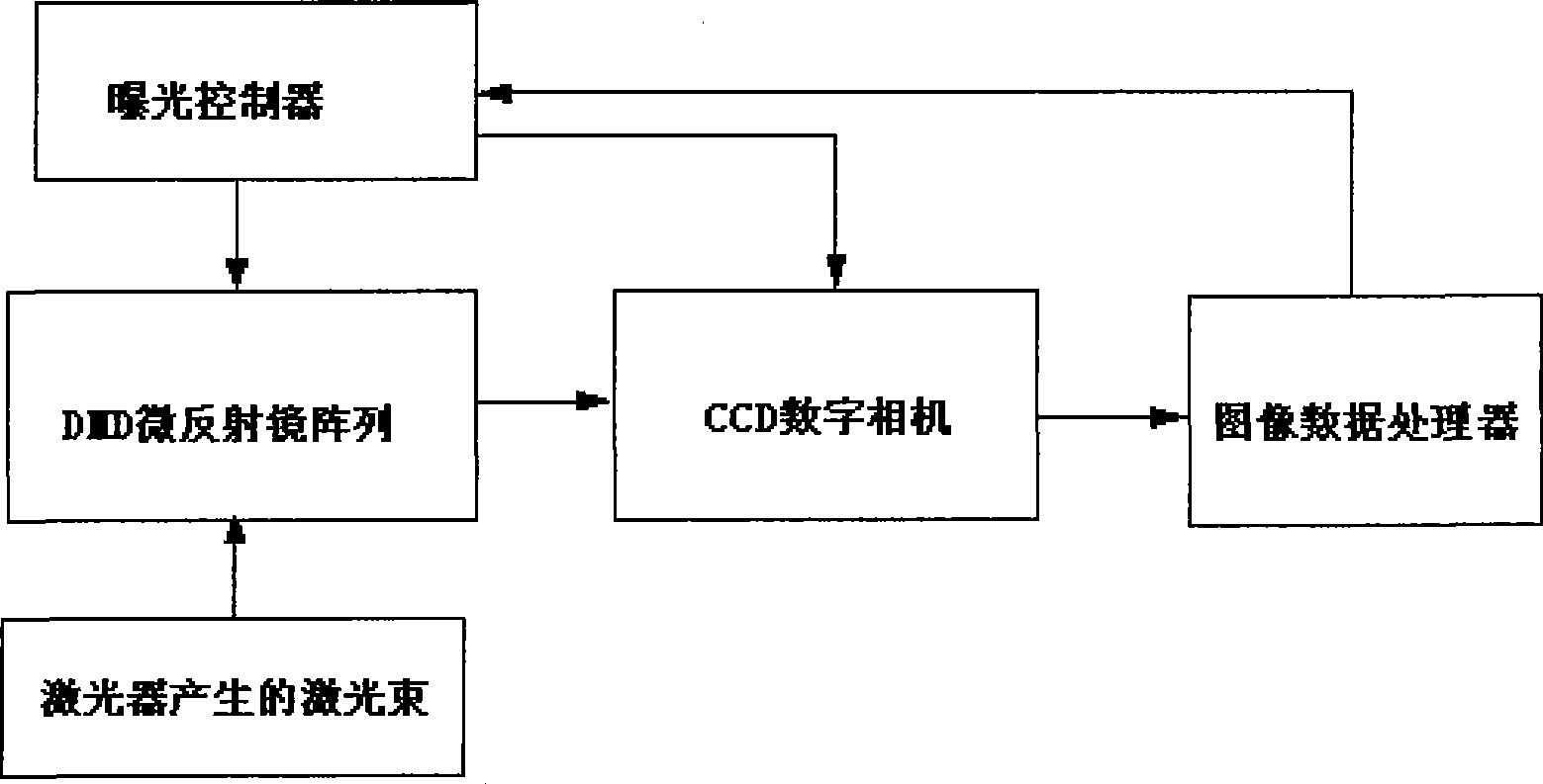
[0021] See attached figure 1 , which is a working principle diagram of the laser spot measuring device of this embodiment. The laser spot measurement device is composed of DMD micro-mirror array, CCD digital camera, exposure controller and image data processor. figure 1 Among them, one output terminal of the exposure controller sends out a signal to control the opening and closing of the shutter of the CCD digital camera, and the other output terminal outputs a signal to control the opening state of the working pixel of the DMD micromirror array; the laser beam generated by the laser is projected to the DMD micromirror array. In the center of the mirror array device, the DMD micro-mirror array device reflects the laser beam to the photosensitive surface of the CCD digital camera, and the video signal output end of the digital camera is connected to the image data processor. After being processed by the image data processor, its One output signal is fed back to the control exp...


PUM


Abstract

The invention relates to a laser facula measuring device and a measuring method thereof. The device consists of a DMD micro-mirror array, a digital camera, an exposure control unit and a picture digital processor. The exposure control unit is provided with two output ends which respectively output signals to control the DMD micro-mirror array and the digital camera; and the input end of the picture digital processor is connected with the video signal output end of the digital camera. In the method, DMD micro-mirror array components are utilized, so the characteristics of an incident light path can be changed at different times and in different regions so as to accurately control the exposure process and obtain a laser beam detection image with high dynamic range; and by means of data processing, diameter, ellipticity, position, center, three-dimensional outline, power, and other parameters of the facula can be obtained. As the whole process happens within a short time, the defect that the position and the energy state of the laser facula changes as time goes by can be avoided, and light beam quality of the laser beam can be more accurately measured.

Description


Claims


Application Information

Patent Timeline
Owner SUZHOU UNIV
Why Eureka
Try Eureka