Region overlap control for autorange/autoset functions

一种控制器、显示区域的技术,应用在测量装置、数字变量/波形显示、测量电变量等方向,达到增强查看的效果

Inactive Publication Date: 2009-06-17
TEKTRONIX INC
View PDF0 Cites 2 Cited by
  • Summary
  • Abstract
  • Description
  • Claims
  • Application Information

AI Technical Summary

Problems solved by technology

The small vertical display of the waveform hampers triggering and adversely affects all measurement functions as well as auxiliary functions such as harmonics and switching loss measurements

Method used


Image

  • Region overlap control for autorange/autoset functions
  • Region overlap control for autorange/autoset functions
  • Region overlap control for autorange/autoset functions

Examples


Embodiment Construction

[0015] The objects, advantages and other innovative features of the invention will become apparent from a reading of the following detailed description in conjunction with the appended claims and accompanying drawings.

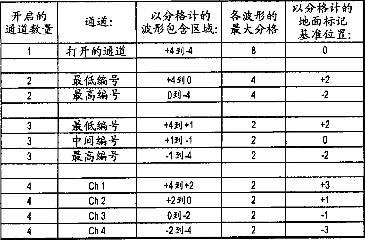
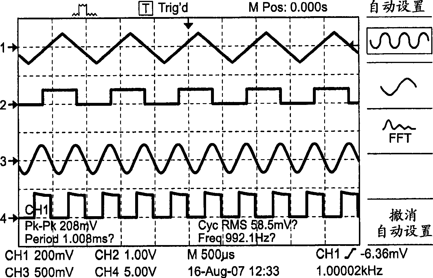
[0016] To achieve a large vertical display of multiple acquired waveforms on the instrument display screen, overlapping waveforms are provided in the Autorange and Autoset functions and during normal instrument operation. Typically in the autorange / autoset function the user is given an option which defines how multiple waveforms are overlaid or displayed. The effect of this feature is to provide more vertical display space for overlapping waveforms, which enhances triggering, all measurement functions, and auxiliary functions as they are enhanced with additional vertical clarity.

[0017] Generally, each waveform is acquired by a different acquisition channel of the instrument and temporarily stored in a corresponding individual acquisition memory or in a segm...


PUM


Abstract

A method of region overlap control for the display of a plurality of waveforms on an instrument includes an overlap function that allows selection by a user of a vertical height on a display screen for each of the waveforms. A ground marker for each of the waveforms is adjusted on the display screen according to the selected vertical height. The result is that the plurality of waveforms are displayed on the display screen in an overlapping fashion with sufficient vertical height to enhance triggering, all measurement functions and secondary functions, such as harmonics and switching loss measurements.

Description

technical field [0001] The present invention relates to instrument use setting, more specifically, relates to the automatic range / automatic setting function of the waveform display instrument. Background technique [0002] Test and measurement instruments that display multiple waveforms simultaneously, such as the TPS2000 Series oscilloscopes manufactured by Tektronix, Inc. of Beaverton, OR, have an autoranging / autoset function that assigns specific waveforms to specific areas on the display screen. Typically, some sort of grid is also displayed, such as a grid with eight (8) major vertical divisions. These main vertical divisions are defined, where the highest waveform display edge is at the +4 division of the display screen, the center of the display screen is at the 0 division, and the lowest waveform display edge is at the -4 division of the display screen. The current autorange / autoset feature assigns waveforms to individual specific areas of the display screen, e.g. ...

Claims


Application Information

Patent Timeline
Patent Type & Authority Applications(China)
IPC IPC(8): G01R13/00
CPCG01R13/00G01R13/30G01R13/0236G01R13/20
Inventor C·H·纳尔逊D·尚克斯E·A·迪金森L·X·朗宁S·C·赫林
Owner TEKTRONIX INC
Why Eureka
Try Eureka