Imaging lens unit and camera module

A camera lens and lens technology, applied in electrical components, image communication, optical components, etc., can solve the problem of inability to shoot high-quality images, and achieve the effects of high image quality and shortened optical length.

Inactive Publication Date: 2009-06-17
HITACHT MAXELL LTD
View PDF1 Cites 2 Cited by
  • Summary
  • Abstract
  • Description
  • Claims
  • Application Information

AI Technical Summary

Problems solved by technology

[0005] However, in the technology described in Patent Document 1, since the back focal length is shortened, the angle of the light rays incident on the imaging surface becomes larger than the vertical angle, so it is impossible to capture high-quality images.

Method used


Image

  • Imaging lens unit and camera module
  • Imaging lens unit and camera module
  • Imaging lens unit and camera module

Examples


Embodiment 1

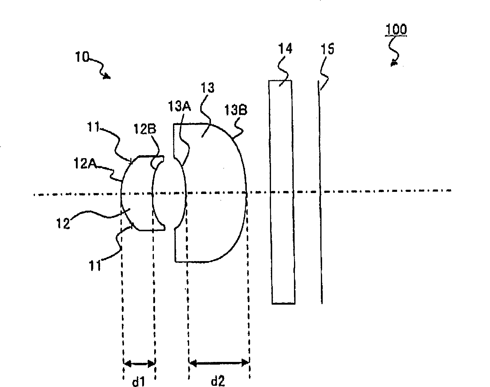
[0064] Next, Embodiment 1 of the present invention will be described. Figure 5 A side view of the camera module 101 according to the first embodiment is schematically shown. again, in Figure 5 Among them, the variable diaphragm 11 from the object side is used as ST (stop (stop) surface), the object side lens surface 12A of the first lens 12 is used as the second surface, and the imaging side of the first lens 12 is The lens surface 12B is used as the 3rd surface, the object side lens surface 13A of the second lens 13 is used as the 4th surface, the imaging side lens surface 13B of the second lens 13 is used as the 5th surface, and the object-side lens surface 13A of the cover glass 14 is used as the 5th surface. The side surface is defined as the sixth surface, the imaging side surface of the cover glass 14 is defined as the seventh surface, and the imaging surface of the imaging element 15 is defined as the eighth surface. In addition, in this embodiment, resin is used fo...

Embodiment 2

[0081] Next, Embodiment 2 of the present invention will be described. Figure 7 It is a side view schematically showing the camera module 102 according to the second embodiment. Again, if Figure 7 As shown, in the camera module 102 of the second embodiment, the configuration other than the first lens 22 and the second lens 23 is substantially the same as that of the camera module 101 of the first embodiment. Accordingly, substantially the same structures are marked with the same symbols, and descriptions thereof are omitted. In addition, in this embodiment, resin is used for both the first lens 22 and the second lens 23 as lens materials, but glass may also be used.

[0082] Again, the same as in Example 1, in Figure 7 Among them, the light amount iris diaphragm 11 is referred to as ST (stop surface) from the object side, the object-side lens surface 22A of the first lens 22 is used as the second surface, and the imaging-side lens surface 22B of the first lens 22 is As t...


PUM


Abstract

The invention provides an imaging lens unit capable of shortening optical length and realizing high image quality and a camera module. The imaging lens unit (10) includes, from an object side, a diaphragm (11) with changeable light quantity, a first lens (12), and a second lens (13) placed on an image side of the first lens (12). The first lens (12) is a positive meniscus lens convex toward the object side, and at least one side of the first lens has an aspherical surface. The second lens (13) is a meniscus lens convex toward the image side, and at least one side of the second lens has an aspherical surface. Further, a maximum value of an angle between a tangent to a surface on the image side of the second lens (13) and a normal to an optical axis is in a range of 65 DEG to 90 DEG within an effective diameter of the second lens.

Description

technical field [0001] The present invention relates to an imaging lens unit and a camera module, in particular to an imaging lens unit composed of two imaging lenses and a camera module having the imaging lens unit. Background technique [0002] In recent years, the miniaturization of imaging elements has been advancing. In addition, along with the miniaturization of imaging elements, the miniaturization of imaging equipment is also advancing. Furthermore, in order to realize downsizing of the camera module, it is desired to develop an imaging lens unit composed of two imaging lenses. However, when this imaging lens unit is used, it is difficult to capture high-quality images. [0003] In order to capture images with better image quality, it is desirable that the light be incident at an angle close to the vertical relative to the imaging element. To make the light incident on the imaging element close to the vertical angle, it is usually necessary to obtain a longer back...

Claims


Application Information

Patent Timeline
Patent Type & Authority Applications(China)
IPC IPC(8): G02B13/00G02B9/10H04N5/225
CPCG02B13/18G02B9/04G02B13/00
Inventor 中西正贵皆川良明
Owner HITACHT MAXELL LTD
Why Eureka
Try Eureka