Wire pair testing drawing board, lens optical parsing and measuring system and measuring method thereof

A test line and resolution technology, applied in the lens optical resolution measurement system and its measurement field, can solve the problems of difficulty in identifying the lens to be measured, no identification, and difficulty in determining the optical axis of the lens, and achieve the measurement value of the optical resolution capability. precise effect

Inactive Publication Date: 2009-06-17
HONG FU JIN PRECISION IND (SHENZHEN) CO LTD +1
View PDF0 Cites 19 Cited by
  • Summary
  • Abstract
  • Description
  • Claims
  • Application Information

AI Technical Summary

Problems solved by technology

[0004] However, since the optical axis of the lens is often difficult to determine accurately, especially as the size of the lens becomes smaller and smaller, it is more difficult to determine the optical axis of the lens.
Existing lens optical analysis measurement systems and their measurement methods often fail to identify or are difficult to identify whether the optical axis of the lens to be tested coincides with the central axis of the image sensor

Method used


Image

  • Wire pair testing drawing board, lens optical parsing and measuring system and measuring method thereof
  • Wire pair testing drawing board, lens optical parsing and measuring system and measuring method thereof
  • Wire pair testing drawing board, lens optical parsing and measuring system and measuring method thereof

Examples


Embodiment Construction

[0017] In the following, the test line provided by the present invention will be further described in detail with respect to the drawing board, the lens optical analysis measurement system and the measurement method thereof in conjunction with the accompanying drawings.

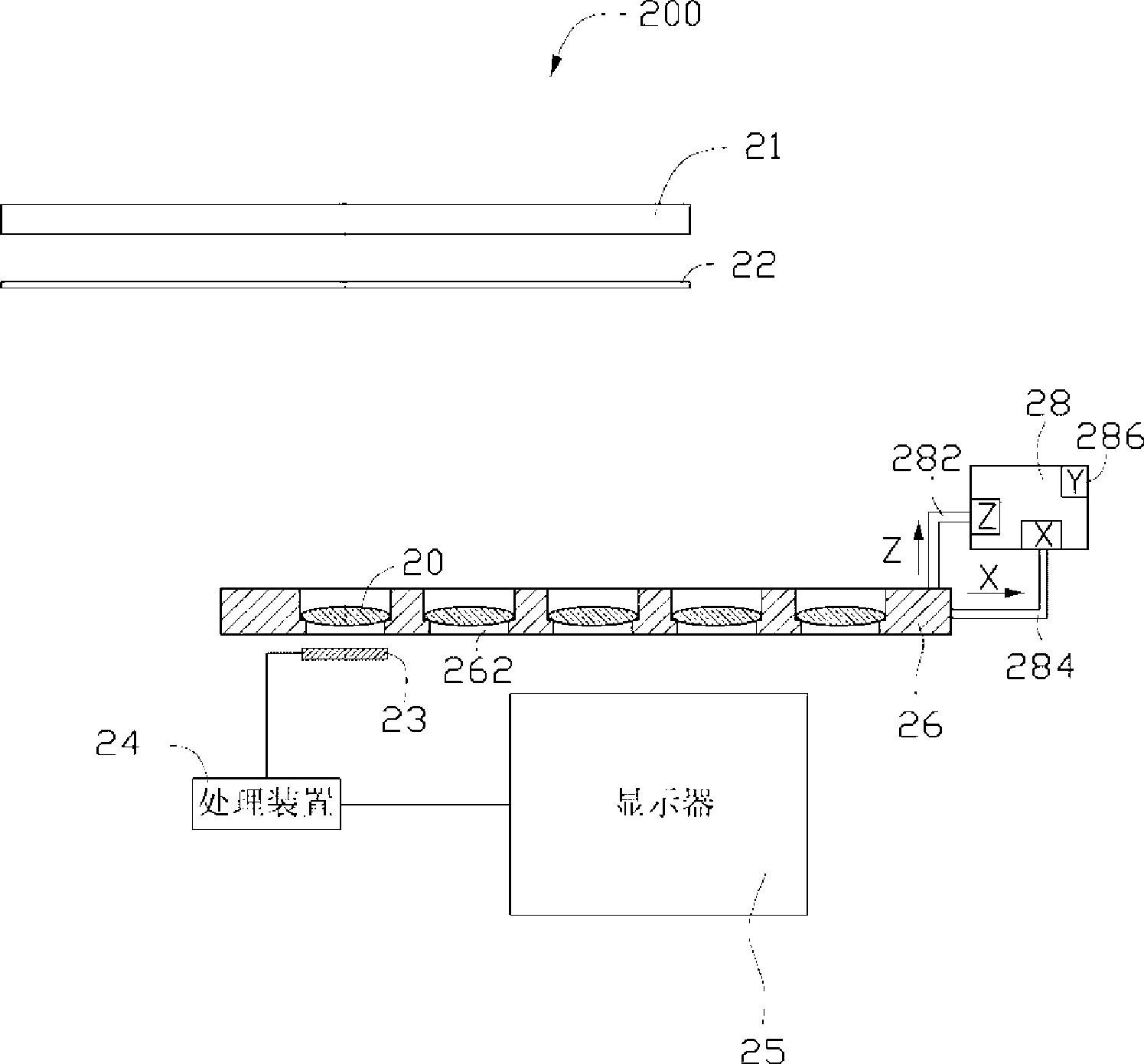
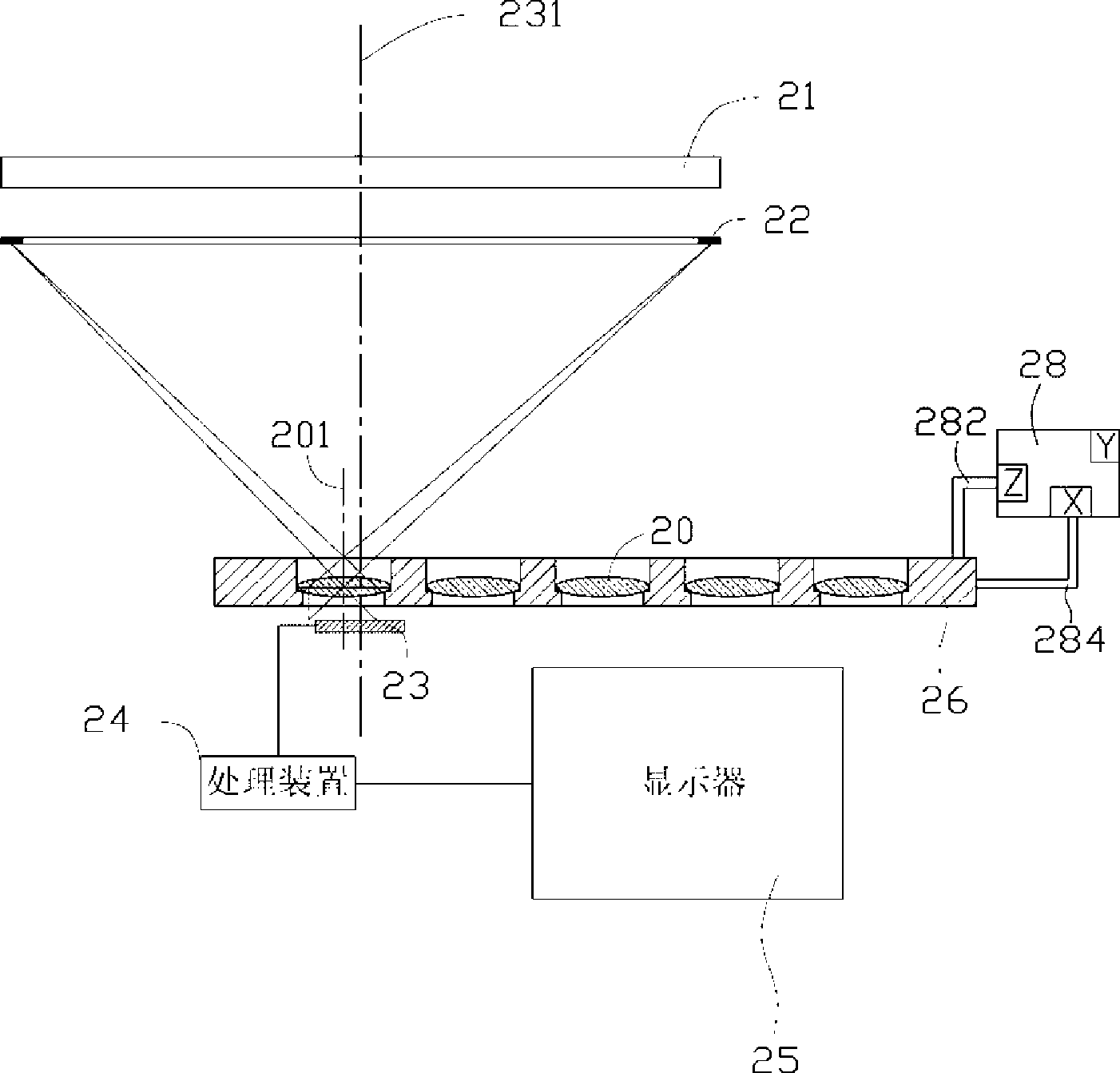
[0018] Please also refer to figure 1 and figure 2 , the lens optical analysis measurement system 200 provided by the embodiment of the present invention includes a light source device 21, a test line pair chart 22, an image sensor 23, a processing device 24, a display 25, a hollow bearing Disk 26 and a drive device 28 for driving the carrier disk 26 .

[0019] The light source device 21 can be an LED device for emitting light to illuminate the test line pattern board 22 .

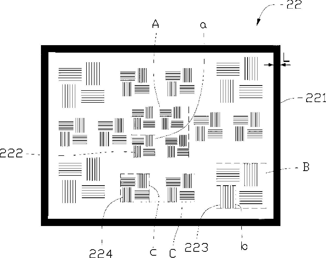
[0020] The test line pair chart 22 has a thickened frame pattern 221 , which is located on the edge of the entire test line pair chart 22 , has a rectangular shape, and is symmetrical about the center of the entire test line pair chart...


PUM


Abstract

The invention provides a test line pair drawing board which is provided with a bold frame-shaped pattern and a plurality of test line pair figures, wherein, the bold frame-shaped pattern is centrally symmetrical about the entire test line pair drawing board, and the test line pair figures are positioned within the bold frame-shaped pattern. The invention also provides a lens optical analysis and measurement system including the test line pair drawing board, a light source, an image sensor, a processing device and a display device, wherein, a lens is corresponding the test line pair drawing board to be measured; the light source is used for emitting light to irradiate the test line pair drawing board; the image sensor is used for receiving an optical signal that the light reflected by the test line pair drawing board penetrates through the lens to be measured and for converting the optical signal into an electric signal; the processing device is used for receiving the electric signal from the image sensor and converting the electric signal into a digital signal to calculate and output brightness distribution data and optical analysis modulation and conversion function values; and the display device is used for receiving and displaying the output brightness distribution data and optical analysis modulation and conversion function values. The invention also provides an optical analysis measurement method for the lens.

Description

technical field [0001] The invention relates to a test line pair diagram board for measuring the optical resolution capability of a lens, and relates to a lens optical resolution measurement system and a measurement method thereof. Background technique [0002] A camera module usually includes at least one lens and an image sensor opposite to the lens, and is widely used in camera devices for various purposes. The camera module is built into various portable electronic devices, such as mobile phones, video cameras Machines and computers are favored by many consumers. [0003] The measurement of the optical resolution capability of the lens is usually completed by a lens optical resolution measurement system. The working principle of the lens optical analysis measurement system is to use digital image processing to directly calculate the physical optical analysis Modulation Transfer Function (MTF) to characterize the optical analysis capability of the lens. Such as Figure ...

Claims


Application Information

Patent Timeline
Patent Type & Authority Applications(China)
IPC IPC(8): G03B43/00G01M11/00G01M11/02
CPCG01M11/0221G01M11/0292
Inventor 袁崐益
Owner HONG FU JIN PRECISION IND (SHENZHEN) CO LTD
Why Eureka
Try Eureka