
Imaging unit and image forming apparatus using same

A technology for imaging components and components, which is applied to the equipment of electrical recording technology applying charge patterns, electrical recording technology and instruments applying charge patterns, etc., can solve the problem of low production efficiency, improve productivity, and facilitate high-precision management. , the effect of easy installation

Inactive Publication Date: 2009-06-17
RICOH KK
View PDF2 Cites 0 Cited by
  • Summary
  • Abstract
  • Description
  • Claims
  • Application Information

AI Technical Summary

Problems solved by technology

However, this method is not efficient because it requires adjustment of the distance between axes.

Method used


Image

  • Imaging unit and image forming apparatus using same
  • Imaging unit and image forming apparatus using same
  • Imaging unit and image forming apparatus using same

Examples


Embodiment Construction

[0025] Embodiments of the present invention are described below with reference to the drawings.

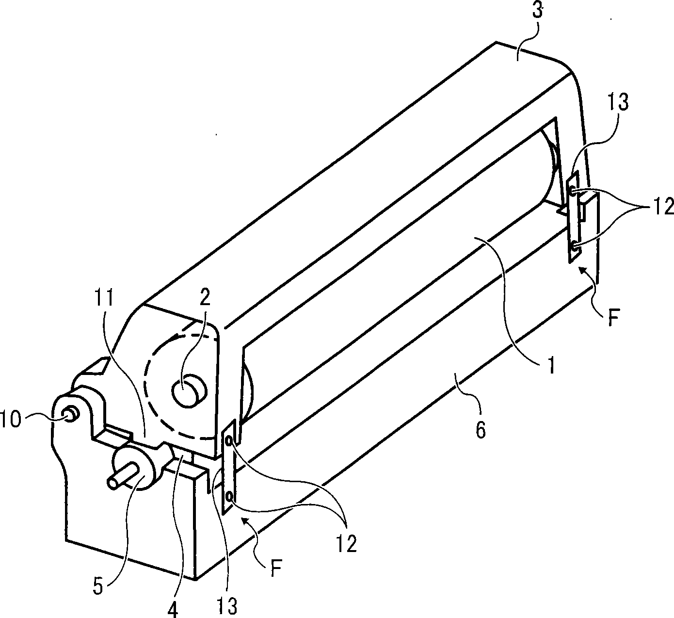
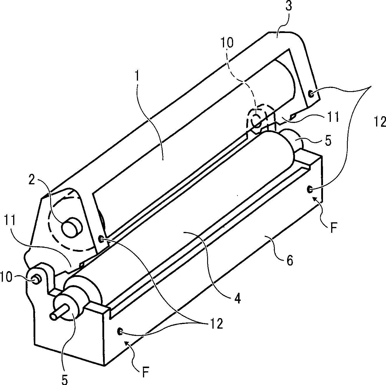
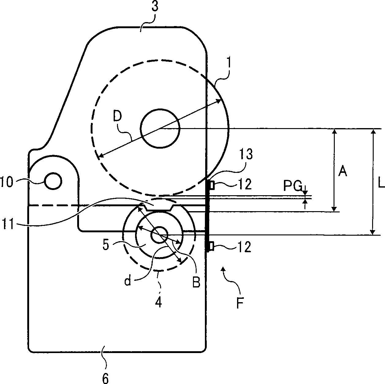
[0026] figure 1 Shown is a side view of a schematic configuration of the imaging unit according to this embodiment. exist figure 1 In the imaging unit, a photoreceptor drum 1 as an image carrier is held rotatably in a photoreceptor unit (hereinafter referred to as PCU) frame 3 via bearings 2 at both end flanges (not shown). In addition, after the developing roller 4 is supported by the support member 5 embedded in the flange shaft at both ends, it is parallel to the axis of the photoreceptor drum 1 on the upper part of the developer cartridge 6 of the developer unit holding the developer through the support member 5 was shelved. The PCU housing 3 and the developer cartridge 6 are connected so as to be rotatable by a common rotation shaft 10 arranged parallel to the photoreceptor drum shaft 1. By rotating around the common rotation shaft 10, the photoreceptor drum 1 and the deve...


PUM


Abstract

An electrophotographic imaging unit includes a photoconductor housing, a developer housing, and a support. The photoconductor housing is configured to rotatably support a photoconductor drum. The developer housing is configured to accommodate developer and a developer roller. The support is configured to rotatably support the developer roller at opposite ends thereof. The photoconductor housing and the developer housing are hinged together at one side, and movable relative to each other at another side to open and close the imaging unit to sandwiched the support between the photoconductor housing and the developer housing when the imaging unit is closed.

Description

technical field [0001] This description relates to image forming equipment such as copiers, facsimile machines, and printers, and image forming units used therein. Background technique [0002] In the image forming apparatus described above, since the processing pitch of the gap between the photoreceptor of the image carrier and the developing roller has a great influence on the image quality, it is necessary to perform high-precision management. In the prior art, the photoreceptor shaft or the developing roller shaft is movably held in the frame of each assembly by assembling the photoreceptor assembly holding the photoreceptor and the developing assembly holding the developer and the developing roller into an imaging assembly. made up. Then, in an operation process of assembling the photoreceptor assembly and the developing assembly, an interaxial distance adjusting member is used to adjust the interaxial distance between the photoreceptor shaft and the developing roller ...

Claims


Application Information

Patent Timeline
Patent Type & Authority Applications(China)
IPC IPC(8): G03G21/18G03G15/00
CPCG03G21/1821G03G21/1825
Inventor 加藤伸一
Owner RICOH KK
Learn More