
Floating control type coolant expansion apparatus

A technology of expansion device and refrigerant, which can be used in refrigerators, liquid level control, refrigeration components, etc., and can solve problems such as complex devices

Active Publication Date: 2009-06-24
IND TECH RES INST
View PDF2 Cites 2 Cited by
  • Summary
  • Abstract
  • Description
  • Claims
  • Application Information

AI Technical Summary

Problems solved by technology

However, this device must use a control valve to control the amount of gas entering the ventilation line, making the device more complicated

Method used


Image

  • Floating control type coolant expansion apparatus
  • Floating control type coolant expansion apparatus
  • Floating control type coolant expansion apparatus

Examples


Embodiment Construction

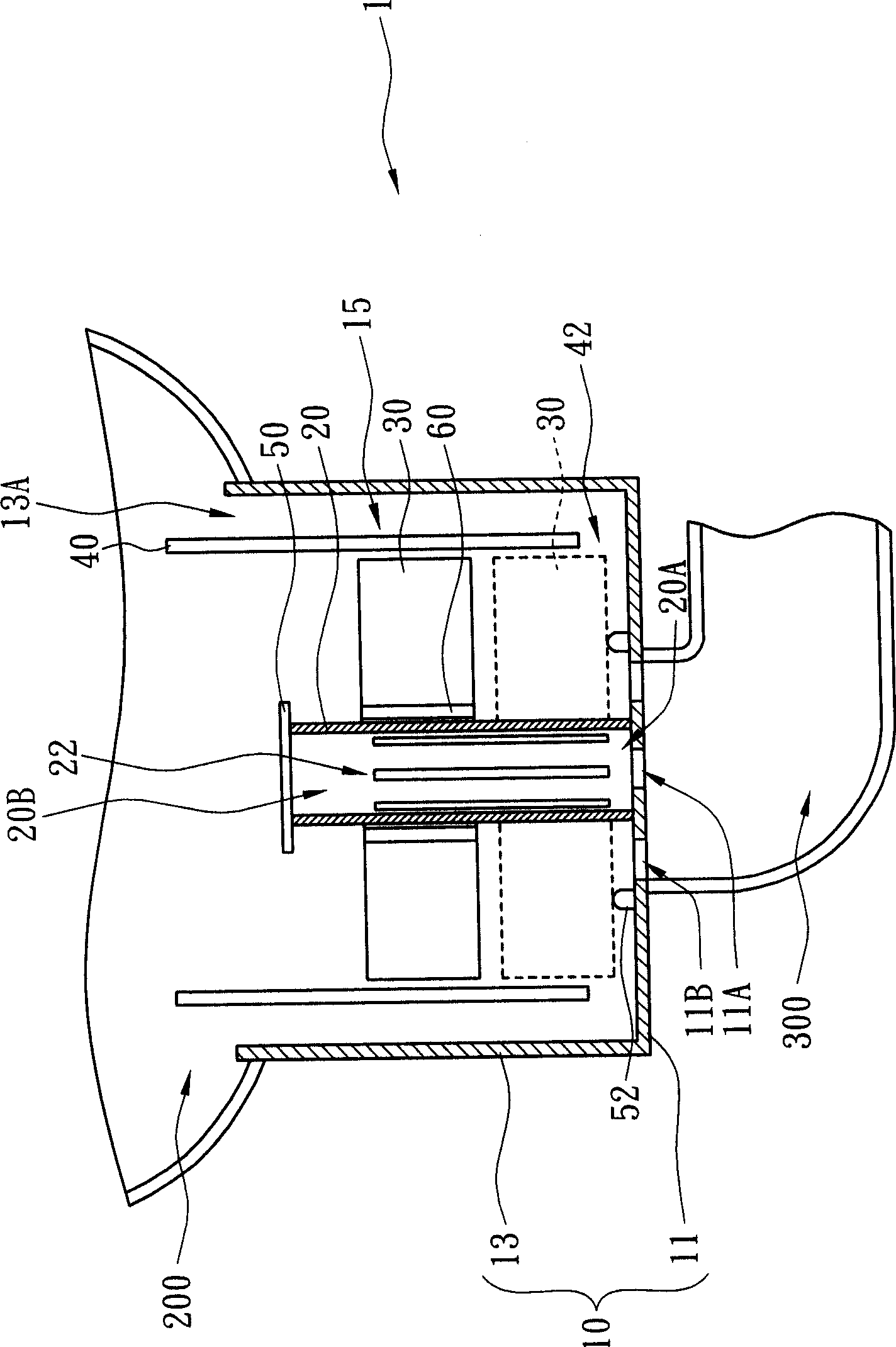
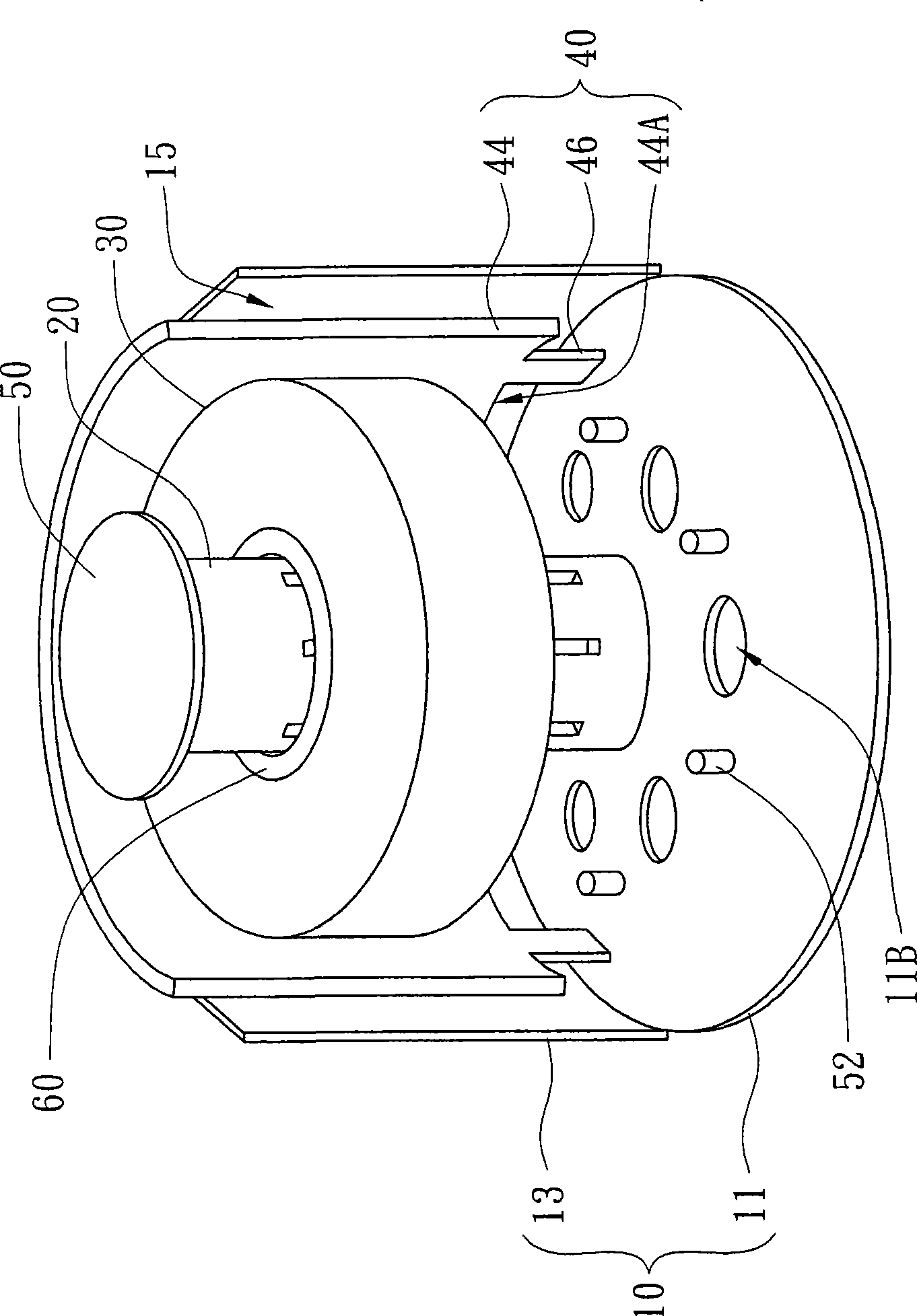
[0051] Please refer to figure 1 , figure 2 , figure 1 A schematic diagram showing a floating refrigerant expansion device according to a preferred embodiment of the present invention, figure 2 draw figure 1 A perspective view of a floating refrigerant expansion device. The float-controlled refrigerant expansion device 1 includes a buoy chamber body 10 , a vertical pipe 20 , a buoy assembly 30 and a partition assembly 40 . The buoy chamber body 10 includes a bottom plate 11 and a tubular shell 13 . The bottom plate 11 is connected to the tubular shell 13 and is provided with a first nozzle 13A opposite to the upper end of the tubular shell 13 . The bottom plate 11 has a first through hole 11A and a plurality of second through holes 11B. The upright tube 20 is fixed on the bottom plate 11 and has a second nozzle 20A and a third nozzle 20B. Wherein, the second nozzle 20A communicates with the first through hole 11A, and each second through hole 11B on the bottom plate 11...


PUM


Abstract

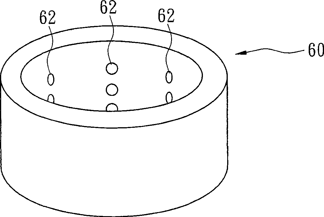
The invention discloses a float refrigerant expansion device comprising a float chamber body, a vertical pipe fitting, a float component and a separation component. The float chamber is connected with a bottom plate and a tubular outer casing, and the bottom plate is provided with a first pipe orifice relative to the upper end of the tubular outer casing and comprises a first through hole and a plurality of second through holes. The vertical pipe fitting is fixed on the bottom plate and comprises a second pipe orifice and a third pipe orifice, the second pipe orifice is communicated with the first through hole, and the second through holes on the bottom plate are positioned at the outside of the junction of the vertical pipe fitting and the bottom plate. At least one opening is formed on the pipe wall of the vertical pipe fitting which is adjacent to the side of the second pipe orifice. The float component is sleeved on the vertical pipe fitting for controlling the orifice area of the opening. The separation component is arranged on the bottom plate along the periphery of the float component, thereby constituting an inner flow channel with the tubular outer casing. A plurality of fluid through holes are formed on the separation component which is adjacent to the bottom plate.

Description

technical field [0001] The invention relates to a refrigerant expansion device, and in particular to a floating control type refrigerant expansion device. Background technique [0002] Refrigeration and air-conditioning systems have become a necessity of human life, especially in the case of highly developed industries, the dependence on large-scale refrigeration and air-conditioning systems is increasing day by day. However, such large systems often have the problem of not having a good expansion device available. Especially after the refrigeration system has entered into new technologies such as systematization, multi-stage adjustable or frequency conversion control, manufacturers' demand for expansion devices has increased. [0003] With the development of refrigeration systems, various expansion devices such as orifice plates, short tubes, temperature-sensitive expansion devices, and electronic expansion devices have also been developed and used. However, these expansio...

Claims


Application Information

Patent Timeline
Patent Type & Authority Applications(China)
IPC IPC(8): F25B41/06G05D9/02
Inventor 刘家宏刘中哲江时昌江旭政
Owner IND TECH RES INST
Learn More