Projection apparatus with cooling structure

A heat dissipation structure and projector technology, applied in the field of projectors, can solve the problems of shortening the service life of the projector and reducing the working efficiency of the projector, and achieve the effect of rapid heat dissipation

Inactive Publication Date: 2009-06-24
FU ZHUN PRECISION IND SHENZHEN +1
View PDF0 Cites 5 Cited by
  • Summary
  • Abstract
  • Description
  • Claims
  • Application Information

AI Technical Summary

Problems solved by technology

Since the projector is a high-precision optical-mechanical-electrical integration product, its internal components are very sensitive to temperatur

Method used


Image

  • Projection apparatus with cooling structure
  • Projection apparatus with cooling structure
  • Projection apparatus with cooling structure

Examples


Embodiment Construction

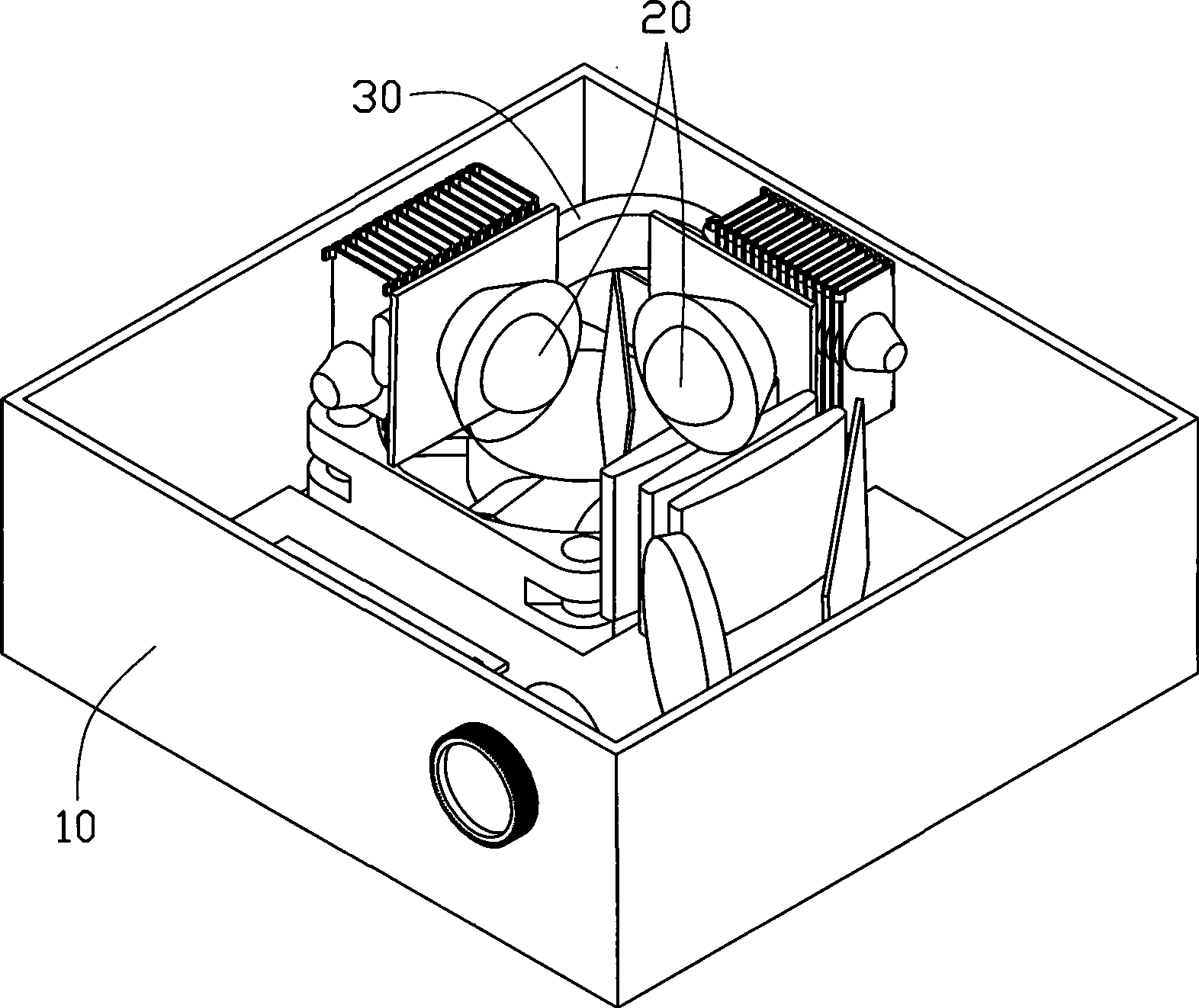
[0012] see figure 1 and figure 2 The projector with heat dissipation structure of the present invention includes a case 10 , two light sources 20 placed in the case 10 , and a heat dissipation structure 30 located in the case 10 and connected to the two light sources 20 .

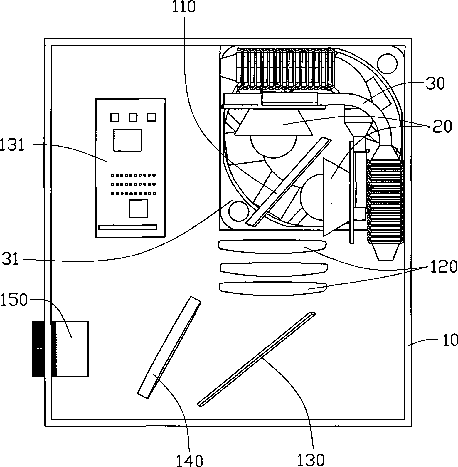
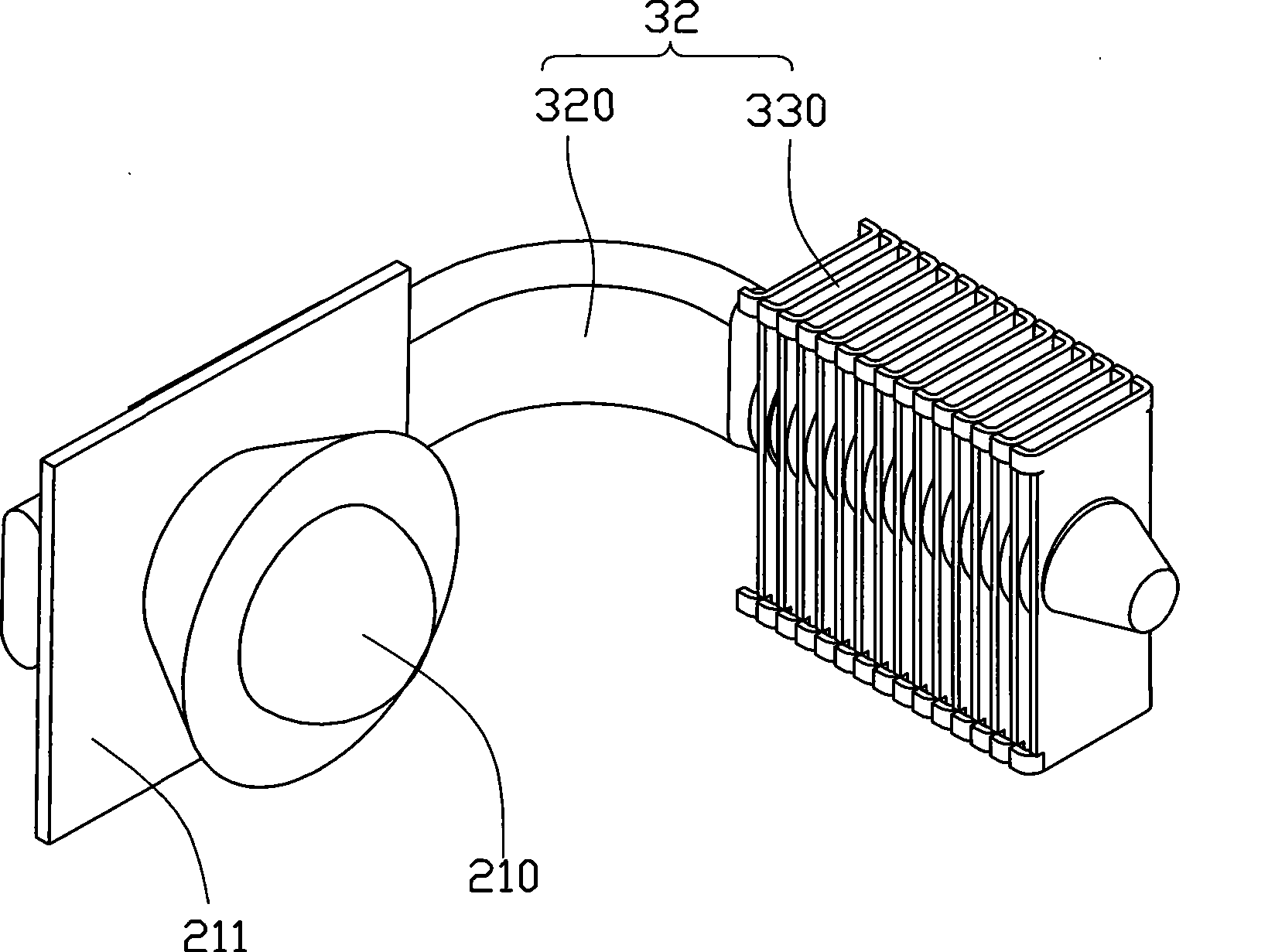
[0013] Please also see image 3 , the above-mentioned case 10 is a square casing, and the above-mentioned two light sources 20 are located at one side of the case 10 . In this embodiment, each light source 20 is a light emitting diode bulb, which includes a circuit board 211 and a light emitting diode 210 installed on the circuit board 211 . The circuit boards 211 of the two light sources 20 are perpendicular to each other in the housing 10 , and the light emitting directions of the two light emitting diodes 210 are vertical.

[0014] A first condenser mirror 110 is disposed between the two light sources 20 , and the light emitted by the two light sources 20 passes through the condenser mirror 110 and t...


PUM


Abstract

A projector provided with a radiating structure comprises a crate, a light source positioned in the crate, and a radiator combined with the light source; and the radiator comprises a heat pipe close to the light source and a fin group far away from the light source and connected with the heat pipe. Heat produced by the light source is transmitted to the fin group through the heat pipe and then dissipated out; and the heat dissipation is rapid.

Description

technical field [0001] The invention relates to a projector, in particular to a projector with a heat dissipation structure. Background technique [0002] With the advancement of projection technology, the application of digital projectors capable of outputting high resolution and large images is becoming more and more extensive. In order to make the projector meet the requirements of high brightness and definition, a high-power bulb module is often used as the light source of the projector. However, a large amount of heat is generated when the high-power light bulb module is in operation. Moreover, with the gradual expansion of the demand for portable and ultra-portable projectors, the weight of projectors continues to decrease and the appearance becomes smaller and smaller, which leads to higher and higher temperatures inside the projectors. Since the projector is a high-precision optical-mechanical-electrical integration product, its internal components are very sensiti...

Claims


Application Information

Patent Timeline
IPC IPC(8): G03B21/16H05K7/20
Inventor 李旭邓根平陈俊吉
Owner FU ZHUN PRECISION IND SHENZHEN
Why Eureka
Try Eureka