Laser marking control card

A laser marking and laser marking machine technology, applied in printing devices, printing and other directions, can solve the problems of poor control stability, slow control speed, poor compatibility, etc., to filter electromagnetic interference, speed up heat dissipation, power consumption small effect

Active Publication Date: 2011-01-19
HANS LASER TECH IND GRP CO LTD
View PDF3 Cites 12 Cited by
  • Summary
  • Abstract
  • Description
  • Claims
  • Application Information

AI Technical Summary

Problems solved by technology

[0003] The purpose of the embodiment of the present invention is to provide a laser marking control card, aiming to solve the problems of slow control speed, poor control stability and high power consumption in the existing laser marking control card
(poor compatibility with peripheral devices)

Method used


Image

  • Laser marking control card
  • Laser marking control card

Examples


Embodiment Construction

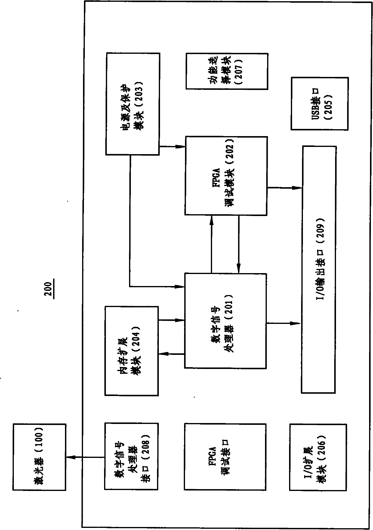
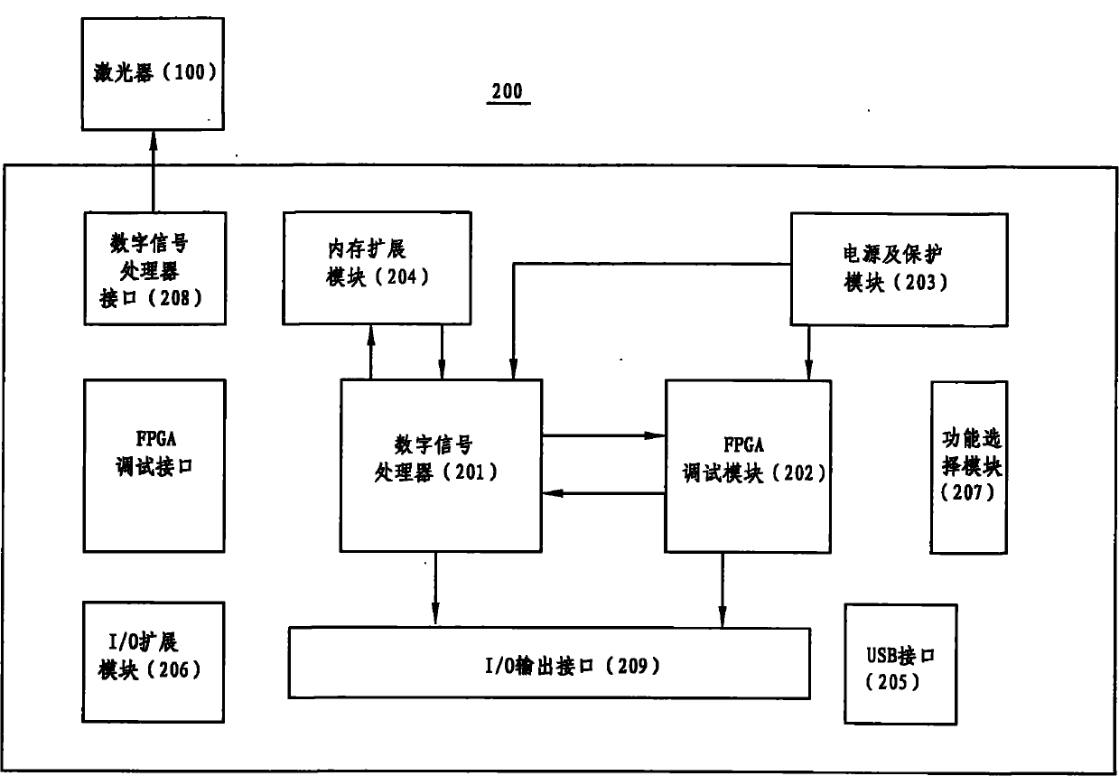
[0017] figure 1 For the structure of the laser marking machine of the present invention, the laser marking machine includes a laser 100 and a laser marking control card 200, and the laser marking control card 200 includes a digital signal processor 201, an FPGA module 202, a power supply and a protection module 203, and a memory An expansion template 204 , a USB communication interface 205 , an I / O expansion interface 206 , a function selection module 207 , a digital signal processor interface 208 , and an output interface 209 .

[0018] The digital signal processor 201 processes the marking data in real time, and the digital signal processor 201 adopts a DSP processor, because the DSP processor consumes less power and has a stronger computing power.

[0019] The FPGA module 202 is connected with the digital signal processor 201 and is responsible for realizing the logic circuit and controlling the laser 100 of the laser marking machine. (The function of "controlling the lase...


PUM


Abstract

The invention relates to a laser marking control card for a laser marker. The laser marking control card comprises a digital signal processor, a field programmable gate array (FPGA) module, a memory extended module and a USB communication interface, wherein the digital signal processor performs real time treatment on marking data; the FPGA module is connected with the digital signal processor andis in charge of implementation of a logical circuit and controls a laser device of the laser marker; the memory extended module is connected with the digital signal processor and enlarges the memory space of the digital signal processor; and the USB communication interface is connected with the digital signal processor and transmits a digital signal processor program of an upper computer to the digital signal processor. In the invention, a special protective circuit is used, so electromagnetic interference is effectively filtered; and the digital signal processor (DSP) with low power consumption, stronger processing capability and customized high-performance is used as a processor, and a method for cladding copper at a large area is adopted to quicken emission of heat, thereby achieving continuous marking within 7*24h.

Description

【Technical field】 [0001] The invention belongs to the field of laser equipment, in particular to a laser marking control card and a laser marking machine. 【Background technique】 [0002] The electromagnetic environment of the working place where the laser marking machine is located is relatively complex. If the marking control card does not properly handle the electromagnetic interference, light leakage will be inevitable; the previous marking control card consumes a lot of power, so it is difficult to achieve 7*24 Hours of continuous marking; the general control card is not compatible with different brands of lasers, Q drives and galvanometers, which seriously affect the working efficiency of the marking machine. 【Content of invention】 [0003] The purpose of the embodiments of the present invention is to provide a laser marking control card, aiming to solve the problems of slow control speed, poor control stability and high power consumption in the existing laser marking...

Claims


Application Information

Patent Timeline
Patent Type & Authority Applications(China)
IPC IPC(8): B41J29/393B41J2/435
Inventor 陈克胜卫军朝阴波波陈健林高云峰
Owner HANS LASER TECH IND GRP CO LTD
Why Eureka
Try Eureka