
Safety system for motor driven swing door leaf

A safety system, motor-driven technology, applied in the field of safety systems, can solve problems such as large installation space

Active Publication Date: 2009-07-01
盖泽工业(天津)有限公司
View PDF1 Cites 9 Cited by
  • Summary
  • Abstract
  • Description
  • Claims
  • Application Information

AI Technical Summary

Problems solved by technology

[0003] In this known safety system, it is disadvantageous that a large installation space is required on the front of the swing door leaf for the structural unit formed by the slide rail and the sensor housing. For structural and aesthetic reasons, this is not desirable

Method used


Image

  • Safety system for motor driven swing door leaf
  • Safety system for motor driven swing door leaf
  • Safety system for motor driven swing door leaf

Examples


Embodiment Construction

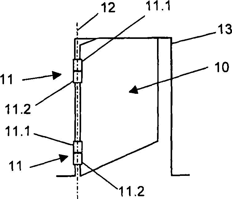
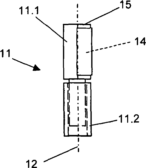
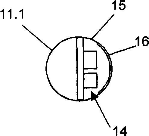
[0024] figure 1 The illustrated swing door leaf 10 is rotatably supported on the door frame 13 adjacent to the attached rectangular door hole via two hinge joints 11 on the left narrow side of the figure. The two hinge joints 11 are usually arranged on the door frame 13 staggered in height, and are respectively formed by two hollow cylindrically wound end regions of the door hinge. The upper door hinges of two hinge joints 11 are fixed on the swing door leaf 10 and thus form the upper sleeve-shaped hinge part 11.1, while the lower door hinge is fixed to the door frame 13 and forms the lower sleeve. A cylindrical hinge part 11.2 with the same diameter. In order to realize the accurate rotation support of the swing door leaf 10 corresponding to the axis of rotation 12, a round shaft pin protrudes from the lower end of the hinge part 11.1, and the shaft pin is inserted into the hole of the hinge part 11.2 located axially downward with a certain gap. . In addition, the swing door le...


PUM


Abstract

The present invention relates to a security system of swing door used on motor drive, which includes a sensor device with at least one sensor, wherein the sensor is set inside the sensor shell that mounted on the narrow side of the swing door, and generates detection field in the move area of the swing door that supported on the doorframe through supervisory signal. The sensor shell is mounted onthe stop dog of the swing door on the narrow side of the doorframe and is constructed and set similar to component part of the hinge moving joint that moves along with the swing door.

Description

Technical field [0001] The invention relates to a safety system for a motor-driven swing door leaf according to the preamble of claim 1. Background technique [0002] Such a safety system for swinging door leaves is known from DE 196 30 877 A1. The swing door leaf is supported on the door frame by two hinges arranged on the narrow side on its right side, and is moved by an electromechanical or electro-hydraulic drive mechanism arranged on the side of the door frame, wherein the electric swinging crank arm is hinged by rotating and sliding The mechanism cooperates with the slide rail fixed on the front of the swing door leaf. The sliding rail composed of extruded profiles is fixedly installed on the door leaf near the upper narrow side and extends almost the entire width of the door leaf. The cross section of the slide rail is enlarged under the actual slide rail profile by a downwardly opening hollow profile, which is closed by a cover that can transmit light. At the end, the hol...

Claims


Application Information

Patent Timeline
IPC IPC(8): E05F15/00E05F15/20E05F15/12E05F15/04
CPCE05F15/203E05F15/0021E05D11/00E05F15/0026E05F2015/0086E05F15/12E05Y2900/132E05Y2600/40E05F2015/0056E05F15/42E05F15/43E05F15/611E05F15/74E05F2015/437E05F2015/483E05Y2400/326
Inventor M·胡克
Owner 盖泽工业(天津)有限公司
Learn More