Supercharge Your Innovation With Domain-Expert AI Agents!

Light emitting diode driving circuit

A technology of light-emitting diodes and driving circuits, which is applied in the directions of circuits, electroluminescent light sources, and electric lamp circuit layout, etc., can solve the problem of increasing the scale of the circuit, and achieve the effect of suppressing the increase of the circuit scale.

Inactive Publication Date: 2012-05-09
MITSUMI ELECTRIC CO LTD
View PDF1 Cites 0 Cited by
  • Summary
  • Abstract
  • Description
  • Claims
  • Application Information

AI Technical Summary

Problems solved by technology

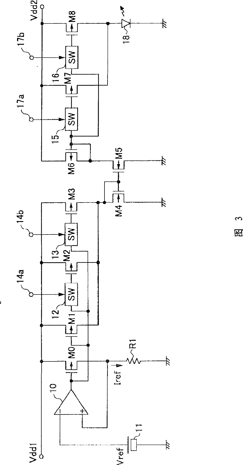
[0015] In this case, in order to finely adjust the luminance of the LED 18, the number of stages of the switches and MOS transistors arranged in parallel with the MOS transistor M1 must be increased from a dozen to several tens, and the circuit scale may increase. question

Method used


Image

  • Light emitting diode driving circuit
  • Light emitting diode driving circuit
  • Light emitting diode driving circuit

Examples


Embodiment Construction

[0040] Embodiments of the present invention will be described below with reference to the drawings.

[0041]

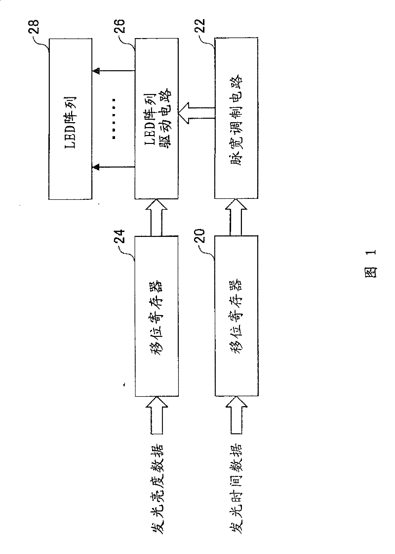
[0042] figure 1 A block diagram showing an embodiment of an LED array device using the light emitting diode driving circuit of the present invention. The LED array device is, for example, a 48-channel structure.

[0043] In this figure, in the shift register 20, 6-bit luminous time data is supplied in time series with, for example, 48 channels for one channel, and after the data is sequentially shifted and latched in the shift register 20, it is It is supplied to the pulse width modulation circuit 22 . The pulse width modulation circuit 22 generates light emission pulses having a pulse width indicated by light emission time data for each channel, and supplies light emission pulses for 48 channels to the LED array drive circuit 26 .

[0044] The shift register 24 is supplied with 6-bit luminescence time data in time series, for example, 48 channels per channel, a...


PUM


Abstract

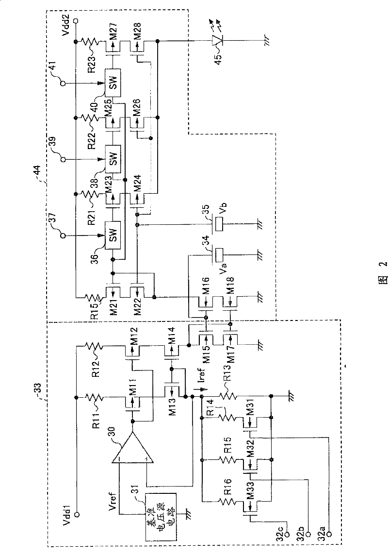
Provided is a light emitting diode driving circuit which can highly accurately adjust emission luminance of a light emitting diode and suppress increase of a circuit size. The light emitting diode driving circuit is composed of a reference current section for generating a reference current, and a current outputting section for generating a driving current based on the reference current by using acurrent mirror circuit and supplying the light emitting diode with the driving current. The reference current section is provided with an operation amplifier which controls the reference current to have a voltage generated by reference current flow in a resistance circuit equal to a fixed reference voltage. The reference current section is also provided with a reference current switching circuit,which is a resistance circuit wherein a plurality of circuits, which connect resistors and transistors in series, with the reference resistors in parallel, voltages generated by the reference currentflow is switched by turning on or off the transistor in the series connection circuit, and the reference current is switched.

Description

technical field [0001] The present invention relates to a light-emitting diode driving circuit, and relates to a light-emitting diode driving circuit for driving each of a plurality of light-emitting diodes arranged. Background technique [0002] As a member for exposing a photoreceptor to light in a printer or the like, an LED array in which light emitting diodes (hereinafter referred to as "LEDs") are arranged in a line is used. As a drive circuit for driving each LED of such an LED array, there are drive circuits described in Patent Documents 1, 2, and the like, for example. [0003] image 3 A circuit configuration diagram showing an example of a conventional light emitting diode drive circuit. This drive circuit is integrated with semiconductors. [0004] In this figure, a reference voltage Vref is applied from a reference voltage source 11 to the inverting input terminal of the operational amplifier 10 . The output terminal of the operational amplifier 10 is connect...

Claims


Application Information

Patent Timeline
Patent Type & Authority Patents(China)
IPC IPC(8): H01L33/00H05B37/02
CPCH05B33/0848H05B45/14
Inventor 山口公一铃木大介
Owner MITSUMI ELECTRIC CO LTD
Features
  • R&D
  • Intellectual Property
  • Life Sciences
  • Materials
  • Tech Scout
  • Unparalleled Data Quality
  • Higher Quality Content
  • 60% Fewer Hallucinations
Learn More