Computer flat knitting machine

A computerized flat knitting machine and needle board technology, which is applied in knitting, weft knitting, textiles and papermaking, etc. It can solve problems such as inaccurate selection of stitches, unreliable push needles, and complex processing of overall castings.

Inactive Publication Date: 2009-07-08
张天林
View PDF0 Cites 4 Cited by
  • Summary
  • Abstract
  • Description
  • Claims
  • Application Information

AI Technical Summary

Problems solved by technology

The computerized flat knitting machine mainly includes machine head assembly, needle plate assembly, creel assembly, transmission assembly, frame assembly, roller assembly, electronic control assembly, bed shifting assembly, and appearance assembly, etc. Composition, wherein the machine head assembly and the needle plate section are the main core parts of the machine. The machine head assembly mainly includes the knitting system and the transfer needle system. The prior art knitting system and the transfer needle system are arranged side by side on a triangular bottom plate In this way, the distance of the entire structure in the horizontal direction is relatively large, the structure is relatively loose, and the production efficiency is not high
And the triangular mechanism cannot transfer or can only transfer in one direction, so the ability of the machine to knit patterns is greatly affected
The needle plate part is mainly composed of the needle plate, the needle selection pins and the knitting needles. The disadvantage of the existing technology is that the needle selection pins are not accurate or the push needles are unreliable, which affects the quality of the knitted fabric.
In addition, the frame of the existing flat knitting machine is made of integral cast iron. Due to the large size of the frame, there are disadvantages such as complex processing of the integral casting, heavy weight, expensive cost, and troublesome movement and transportation.

Method used


Image

  • Computer flat knitting machine
  • Computer flat knitting machine
  • Computer flat knitting machine

Examples


Embodiment Construction

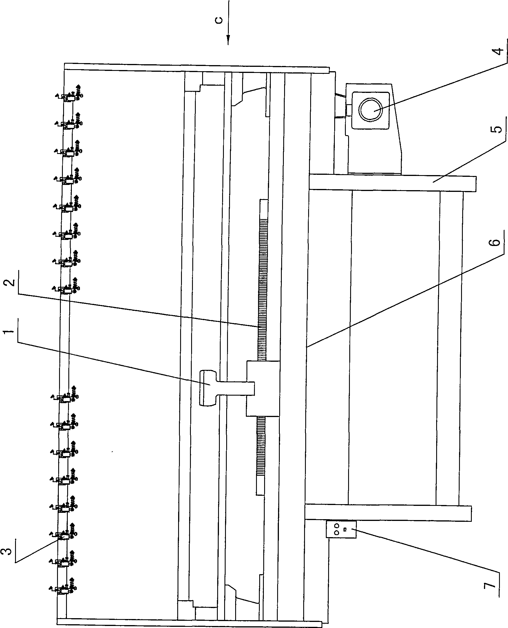
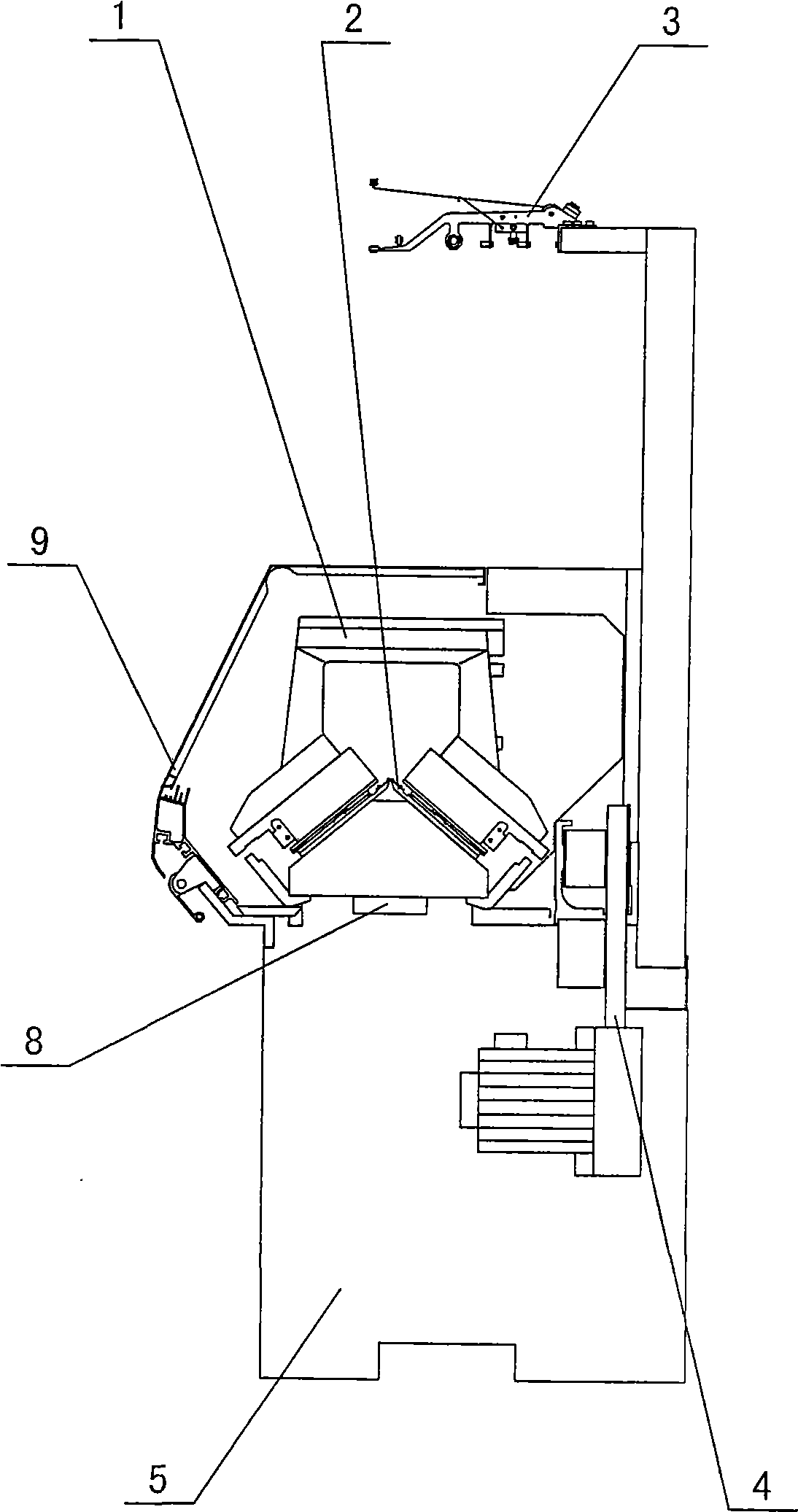
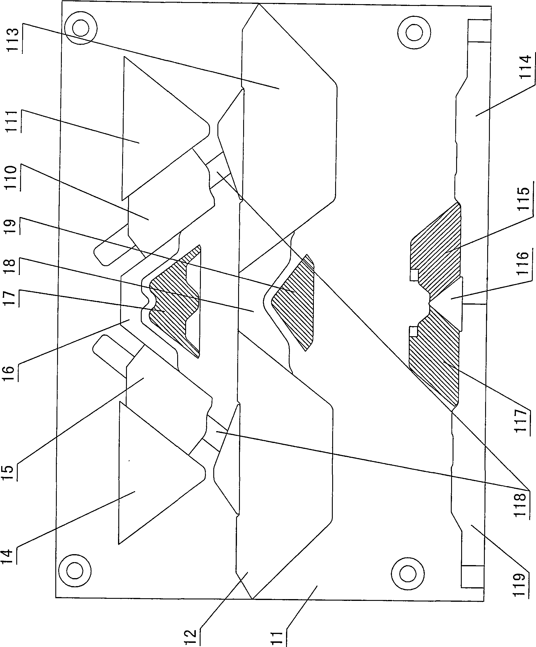
[0015] The invention relates to a computerized flat knitting machine, such as figure 1 — Figure 8 As shown, it includes machine head installation 1, needle plate installation 2, creel installation 3, transmission section installation 4, frame installation 5, roller installation 6, electric control installation 7, bed shifting installation 8 and The outer cover part is composed of 9, and the machine head device 1 includes a knitting system and a needle transfer system arranged on a triangular bottom plate 11. The needle board part includes a needle selection pin 22, a needle board 21 and a knitting needle Needle 23, the selection pin pushes the knitting needle, and the selection pin 22 is formed with a push needle butt 211 and a selection needle butt 212, the push needle butt is in contact with the push needle cam 204, and the selection needle butt is in contact with the needle selection blade 205 , the frame part includes a left wallboard 101, a right wallboard 104, a beam 1...


PUM


Abstract

The invention provides a computer flat knitting machine which includes a head, a needle plate, a creel, a transfer, a frame, a roller, an electric controller, a moving bed and an outer housing. The head includes a knitting system and a stitch receiving needle system, the needle plate includes a selected stitch, a needle plate and a knitting needle, the knitting system and the stitch receiving needle system are set on a same column of a middle position of a triangle bottom plate, the knitting system includes a left stitch triangle, a reverse V shape triangle, a top needle triangle and a right stitch triangle, outside of the left stitch triangle is installed with a left protective needle triangle, outside of the right stitch triangle is installed with a right protective needle triangle, the top needle is installed on back side of the reverse V shape triangle, a left selected needle protective needle triangle and the right selected needle protective needle triangle are installed on two sides of the reverse V shape triangle; the stitch receiving needle system is installed between the left stitch triangle and the right stitch triangle, and locates on front side of the reverse V shape triangle, the stitch receiving needle system includes a stitch triangle and a stitch protective needle triangle located on front side; the selected needle tail part is equipped with a supporting foot, a gap is set on the needle plate tail, the supporting foot and the gap coordinate each other.

Description

technical field [0001] The invention relates to a computerized flat knitting machine, which belongs to the field of knitting machinery. Background technique [0002] Flat knitting machines can be divided into manual flat knitting machines and computerized flat knitting machines, which are widely used in the knitting field. With the continuous improvement of labor costs, manual flat knitting machines have many problems such as high production cost, low efficiency, single variety, poor fabric quality, and unstable performance. Therefore, the computerized flat knitting machine is widely used, and it has the characteristics of labor saving, high efficiency and high degree of automation. The computerized flat knitting machine mainly includes machine head assembly, needle plate assembly, creel assembly, transmission assembly, frame assembly, roller assembly, electronic control assembly, bed shifting assembly, and appearance assembly, etc. Composition, wherein the machine head as...

Claims


Application Information

Patent Timeline
Patent Type & Authority Applications(China)
IPC IPC(8): D04B15/36D04B15/10
Inventor 郑向阳林杰陈金台
Owner 张天林
Why Eureka
Try Eureka