Front and rear regulation structure of hinge for furniture

A technology for front and rear adjustment and furniture, which is used in building structures, door/window accessories, folding panels, etc., can solve the problems of lack of upper and lower limits, low structural rigidity, complicated installation, etc., to achieve stable structure and long service life. , to avoid the effects of long-term use

Active Publication Date: 2009-07-08
伍志勇
View PDF1 Cites 6 Cited by
  • Summary
  • Abstract
  • Description
  • Claims
  • Application Information

AI Technical Summary

Problems solved by technology

The structure has low rigidity, the locking element must be adjusted by tools, and the installation is complicated; in addition, the support arm and the

Method used


Image

  • Front and rear regulation structure of hinge for furniture
  • Front and rear regulation structure of hinge for furniture
  • Front and rear regulation structure of hinge for furniture

Examples


no. 1 example

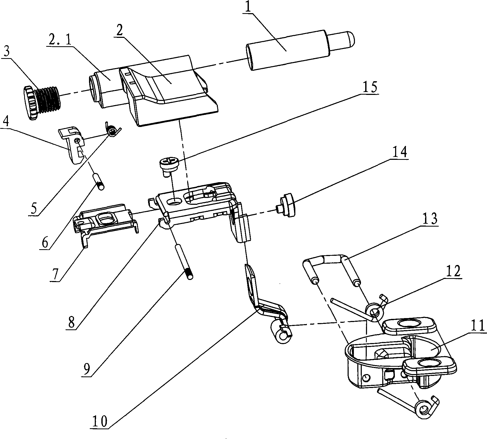
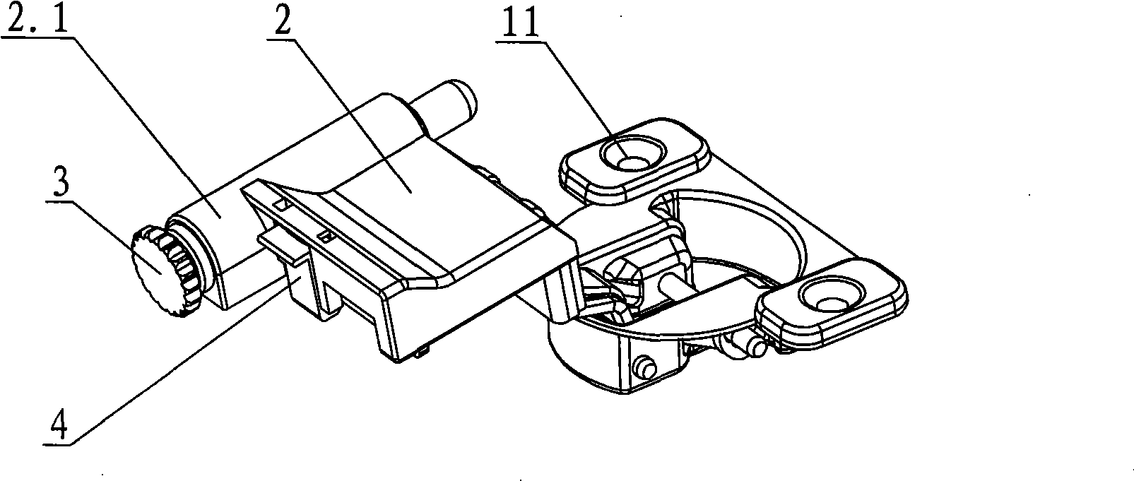
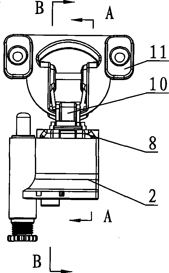
[0036] see Figure 1-Figure 14 , the front and rear adjustment structure of the furniture hinge, including the base 7 connected with the furniture main body 17 and the hinge cup seat 11 hinged with the support arm 10 through the U-shaped pin 13 and the second torsion spring 12 arranged on the left and right sides of the hinge cup seat 11, The base is connected with the support arm through the adjustment cover 8, and a buffer seat 2 is also arranged above the adjustment cover, and the hinge cup seat is arranged on the furniture door body 18, and the two sides of the rear end of the adjustment cover 8 are connected by pins 9, and the buffer The seat 2 is provided with a pull button 4 corresponding to the pin shaft 9, which is fastened with the pin shaft to position the buffer seat perpendicular to the direction of the adjustment cover.

[0037] see Figure 9-Figure 11 , the adjusting cover plate 8 is stamped and formed by sheet metal, the end face is arched, there are notches 8...

no. 2 example

[0042] see Figure 15 , the upper and lower sides of the buffer seat 22 rear end corresponding pins are provided with front and rear limit grooves 22.1 that are upside down U-shaped, connected with the pin 9, the two ends of the pin extend out of the buffer seat up and down both sides and are riveted with it. Other unmentioned parts are the same as the first embodiment.

no. 3 example

[0044] see Figure 16 with Figure 17 , the buffer seat 32 is a square cover shape, and the upper and lower side inner walls are provided with ribs 32.1, and the corresponding ribs on the upper and lower side inner walls of the adjustment cover plate are provided with slots 28.2 to connect with the ribs of the buffer seat to realize front and rear spacing. The buffer seat 32 is arranged outside the adjustment cover plate 28, the side part is provided with a buffer connecting cylinder 32.6, the inner top surface is provided with a positioning bump 32.2 connected with the top surface of the adjustment cover plate 28, and the rear end is also provided with a pull button corresponding to the pull button. Place cavity 32.5. Buffer seat 2 front end upper and lower sides corresponding adjustment cover plate 28 gap is provided with buckle block 32.3, and the rear end also stretches out front limit baffle 32.4 toward adjustment cover plate direction, joins with bearing pin and adjustm...


PUM


Abstract

The invention relates to a front and back adjusting structure of a furniture hinge, which comprises a base connected with a furniture main body and a hinge cup seat arranged on a furniture door body. Adjusting cover plates are glidingly sleeved in front and back on the base and hinged with the hinge cup seat through a supporting arm, two insides of the adjusting cover plates are provided with protrusions or two sides are inwards provided with inner turnover edges, a front sliding groove and a back sliding groove are formed between the protrusions or the inner turnover edges and the inner top surfaces of the adjusting cover plates and connected with the base through a front adjusting convex nail and a back adjusting convex nail, two sides of the base corresponding to the front sliding groove and the back sliding groove are provided with outer turnover edges, and the front sliding groove and the back sliding groove of the adjusting cover plates slide forward and backward along the outer turnover edges by adjusting the front adjusting convex nail and the back adjusting convex nail. The inside of the adjusting cover plates are matched and glidingly connected with the outer turnover edges outside the base through the front sliding groove and the back sliding groove between the protrusions or the inner turnover edges and the top surfaces of the adjusting cover plates, so the adjusting structure has firm structure, simultaneously has the function of limiting up and down, and avoids long-term use and release due to abrasion at the riveted joint between the front and back adjusting convex nails and the base. The adjusting structure has the advantages of simple and reasonable structure, convenient installation, easy production, and long service life.

Description

technical field [0001] The invention relates to a furniture hinge, in particular to a front and rear adjustment structure of a furniture hinge. Background technique [0002] Chinese Patent Document No. CN101298819 discloses a furniture hinge front and rear adjustment structure comprising a saddle supporting a damping cylinder and engaging the first mounting edge of the supporting arm from behind. A locking element movably mounted on the saddle has laterally protruding mounting lugs which, in the locked position, engage the second mounting edge of the support arm from behind. The second mounting edge is oriented opposite the first mounting edge. The structure has low rigidity, the locking element must be adjusted by tools, and the installation is complicated; in addition, the support arm and the mounting plate are slidably and adjustablely connected through the inner and outer sides, and there is no upper and lower limit between them, which is easy to loosen. Contents of t...

Claims


Application Information

Patent Timeline
IPC IPC(8): E05D7/00E05D11/10
Inventor 伍志勇
Owner 伍志勇
Why Eureka
Try Eureka