Micro electromagnetic vibrator

A vibrator and electromagnetic technology, which is applied in the direction of electrical components, electromechanical devices, etc., can solve the problems of electromagnetic interference of commutation sparks, high material requirements, and easy wear and tear, and achieve large effective force, good controllability of features, and long life. long effect

Inactive Publication Date: 2010-09-29
乐清市陆宇微电机有限公司
View PDF6 Cites 0 Cited by
  • Summary
  • Abstract
  • Description
  • Claims
  • Application Information

AI Technical Summary

Problems solved by technology

The micro-vibrator currently used is usually a micro-vibration motor. Whether the micro-vibration motor is cylindrical or flat, it is composed of a motor and an eccentric weight. The rotation of the motor drives the rotation of the eccentric weight to generate vibration. , and these DC motors generally have bearings, brushes and commutators, tungsten alloy eccentric wheels, and the rotor with eccentric wheels rotates unbalanced at high speed. It has higher requirements on the materials of bearings, brushes and commutators. The biggest problem with motors with brushes and commutators is that they are prone to wear, short life, and electromagnetic interference that can generate commutation sparks

Method used


Image

  • Micro electromagnetic vibrator
  • Micro electromagnetic vibrator
  • Micro electromagnetic vibrator

Examples


Embodiment 1

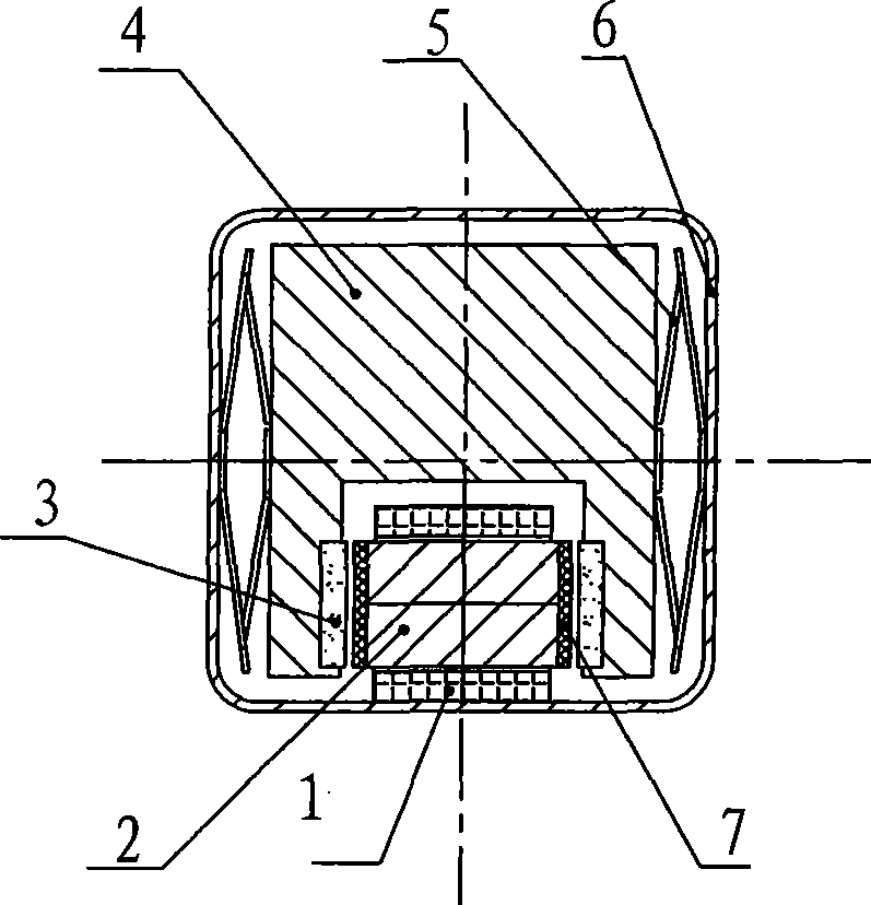
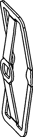
[0022] Such as figure 1 Shown, the miniature electromagnetic vibrator in the present embodiment, by being arranged on the coil 1 in the square shell 6, inline iron core 2, anti-collision pad 7, magnetic steel 3, vibration body 4 and rhombus reed 5 (see figure 2 ), the inline iron core 2, the crash pad 7 and the magnetic steel 3 are all arranged inside the vibrating body 4, and the two ends of the inline iron core 2 are respectively connected with the crash pad 7 and facing one side of the magnetic steel 3, and the magnetic steel The other side of 3 is embedded in the vibrating body 4; there is one in-line iron core 2, which is located in the lower part of the vibrating body 4, has a slightly larger volume, and is wound with a coil 1, and the wires at both ends of the coil 1 are connected to an external power source to vibrate. The body 4 basically fills the square shell 6, and the vibrating body 4 is connected to the shell 6 through the rhombic reed 5. The protruding point on...

Embodiment 2

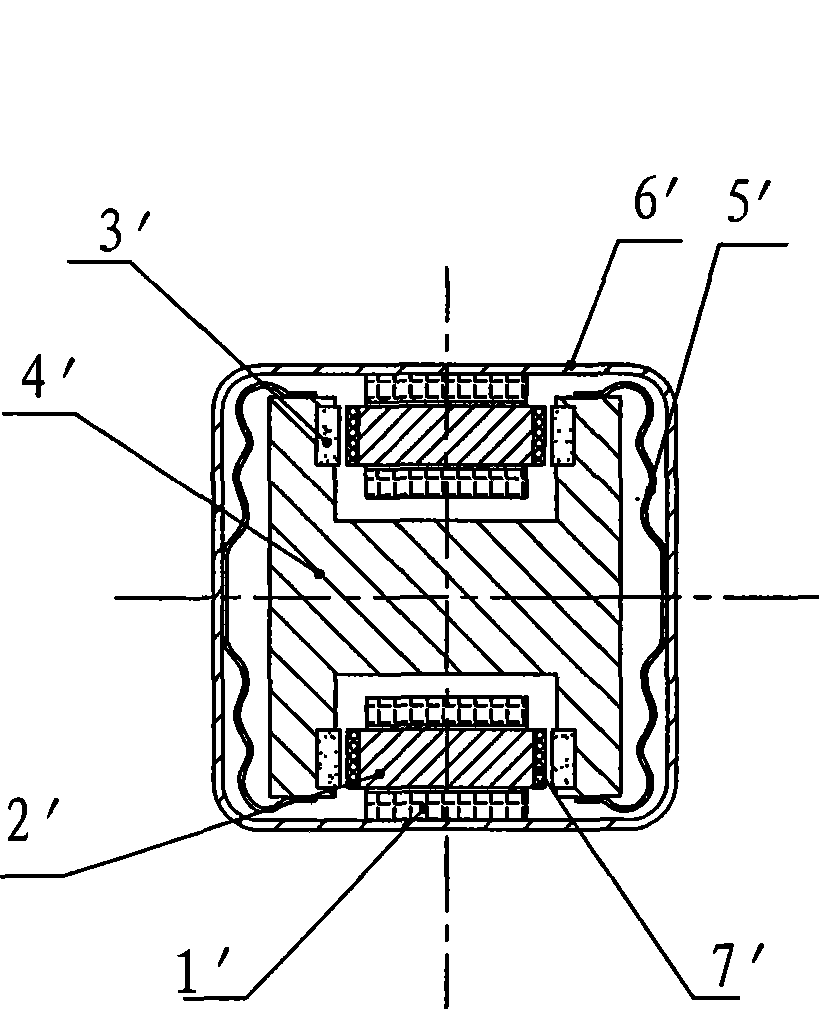
[0026] Such as image 3 As shown, the miniature electromagnetic vibrator in this embodiment consists of a coil 1', an inline iron core 2', a crash pad 7', a magnetic steel 3', a vibrating body 4' and a curve shaped reed 5' (see Figure 4 ), the inline iron core 2', crash pad 7' and magnetic steel 3' are all arranged inside the vibration body 4', and the two ends of the inline iron core 2' are respectively connected to the crash pad 7' and face to One side of the magnetic steel 3', the other side of the magnetic steel 3' is embedded in the vibrating body 4'; there are two in-line iron cores 2', which are respectively located at the upper and lower parts of the vibrating body 4', the volume is slightly smaller, and the upper winding There are two coils 1', the two ends of the two coils 1' are connected in series (the ends are connected) and are drawn out through wires or circuit boards, and connected to an external power supply. The vibrating body 4' basically fills the square ...

Embodiment 3

[0028] Such as Figure 5 As shown, the miniature electromagnetic vibrator in the present embodiment is composed of a coil 1 ", an inline iron core 2 ", a crash pad 7 ", a magnetic steel 3 ", a vibrating body 4 " and a silicon The rubber body 5 "consists of an inline iron core 2", an anti-collision pad 7" and a magnetic steel 3" all arranged inside the vibrating body 4", and the two ends of the inline iron core 2" are respectively connected to the anti-collision pad 7". And facing one side of the magnetic steel 3", the other side of the magnetic steel 3" is embedded in the vibrating body 4"; there is one in-line iron core 2", which is located in the middle of the vibrating body 4", with a slightly larger volume and is wound with Coil 1", the wires at both ends of coil 1" are connected to the external power supply, the vibrating body 4" basically fills the square shell 6", and the vibrating body 4" passes through the hole filled in the gap between the two sides of the vibrating ...


PUM


Abstract

A miniature electromagnetic vibrator comprises a coil arranged in a quadrate housing, a linear iron core, an anti-collision mat, magnetic steel, a vibration body and a jettison device. The linear iron core, the anti-collision mat and the magnetic steel are arranged in the internal of the vibration body, two end surfaces of the linear iron core are respectively connected with the anti-collision mat and is just opposite to one surface of the magnetic steel, and the other surface of the magnetic steel is embedded in the vibration body; one or a plurality of the linear iron cores is / are provided, the coil is wound on the iron core, a lead is led out from the two ends of the coil to be connected with an external power supply, the quadrate housing is basically filed with the vibration body, and the vibration body is connected with the housing through the jettison device. The miniature linear vibrator has the advantages of simple structure, light weight, low manufacturing and material costs, long service life, and no spark and electromagnetic interference.

Description

technical field [0001] The invention relates to a vibrator, in particular to a miniature electromagnetic vibrator used in mobile phones, game machines or electric massage appliances. Background technique [0002] Micro-vibrators are used in mobile phones as silent signal source components; there are other fields that require micro-vibrators such as: game consoles, electric massage appliances, etc. The micro-vibrator currently used is usually a micro-vibration motor. Whether the micro-vibration motor is cylindrical or flat, it is composed of a motor and an eccentric weight. The rotation of the motor drives the rotation of the eccentric weight to generate vibration. , and these DC motors generally have bearings, brushes and commutators, tungsten alloy eccentric wheels, and the rotor with eccentric wheels rotates unbalanced at high speed. It has higher requirements on the materials of bearings, brushes and commutators. The biggest problems with motors with brushes and commutat...

Claims


Application Information

Patent Timeline
Patent Type & Authority Patents(China)
IPC IPC(8): H02K33/18
CPCH02K33/16
Inventor 陆勤高宜杭
Owner 乐清市陆宇微电机有限公司
Why Eureka
Try Eureka