
Filter with replacable insert

A filter and filter element technology, applied in the direction of dispersed particle filtration, chemical instruments and methods, chemical/physical processes, etc., can solve problems such as fluid dynamics is not optimal, and achieve the effect of large channel length

Active Publication Date: 2009-07-08
DONALDSON FILTRATION DEUT GMBH
View PDF4 Cites 1 Cited by
  • Summary
  • Abstract
  • Description
  • Claims
  • Application Information

AI Technical Summary

Problems solved by technology

However the hydrodynamics of this route of inlet and outlet channels are not optimal

Method used


Image

  • Filter with replacable insert
  • Filter with replacable insert
  • Filter with replacable insert

Examples


Embodiment Construction

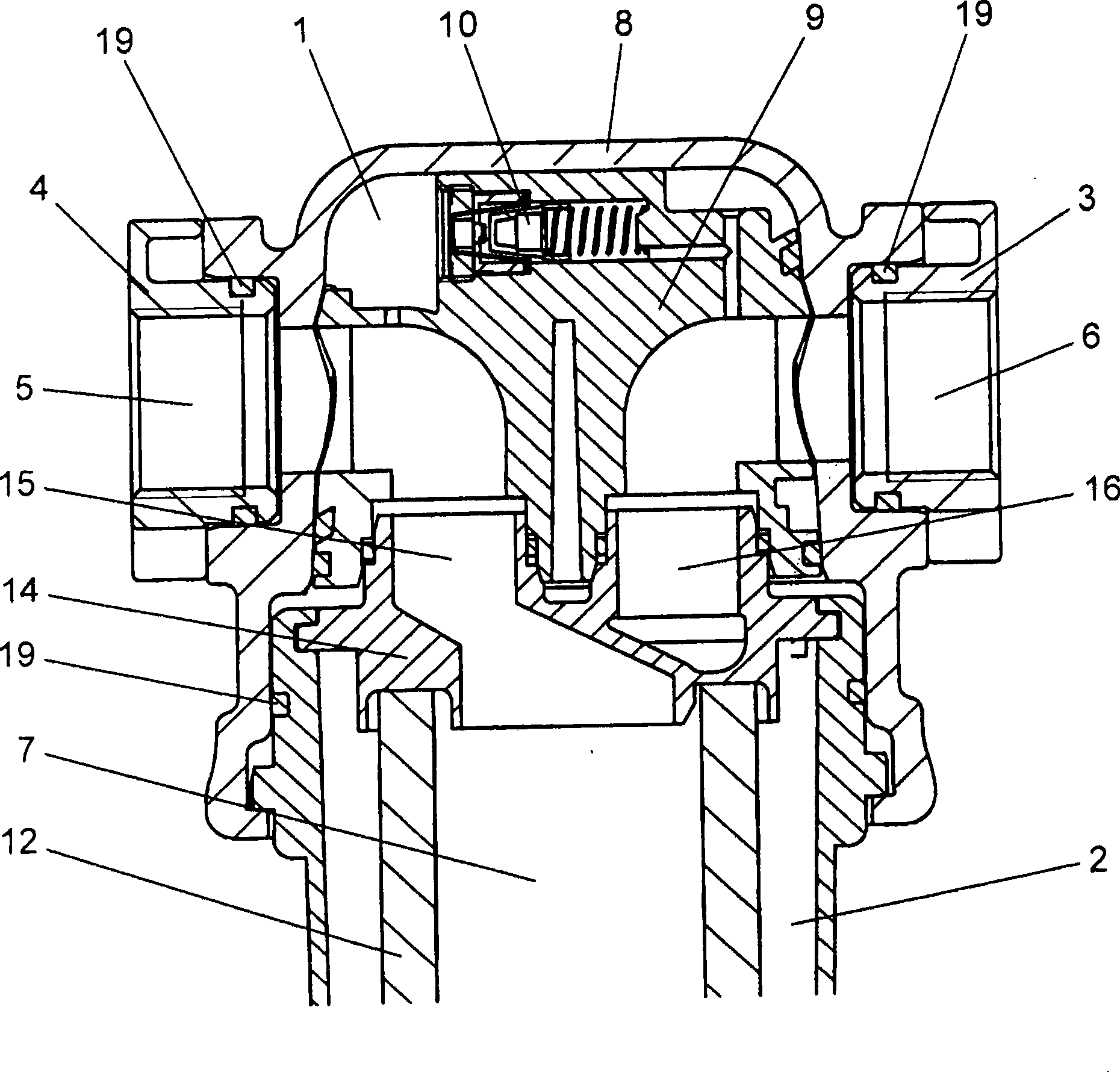
[0036] According to the filter of the first embodiment of the present invention ( figure 1 ) includes filter top 1 and filter bottom 2.

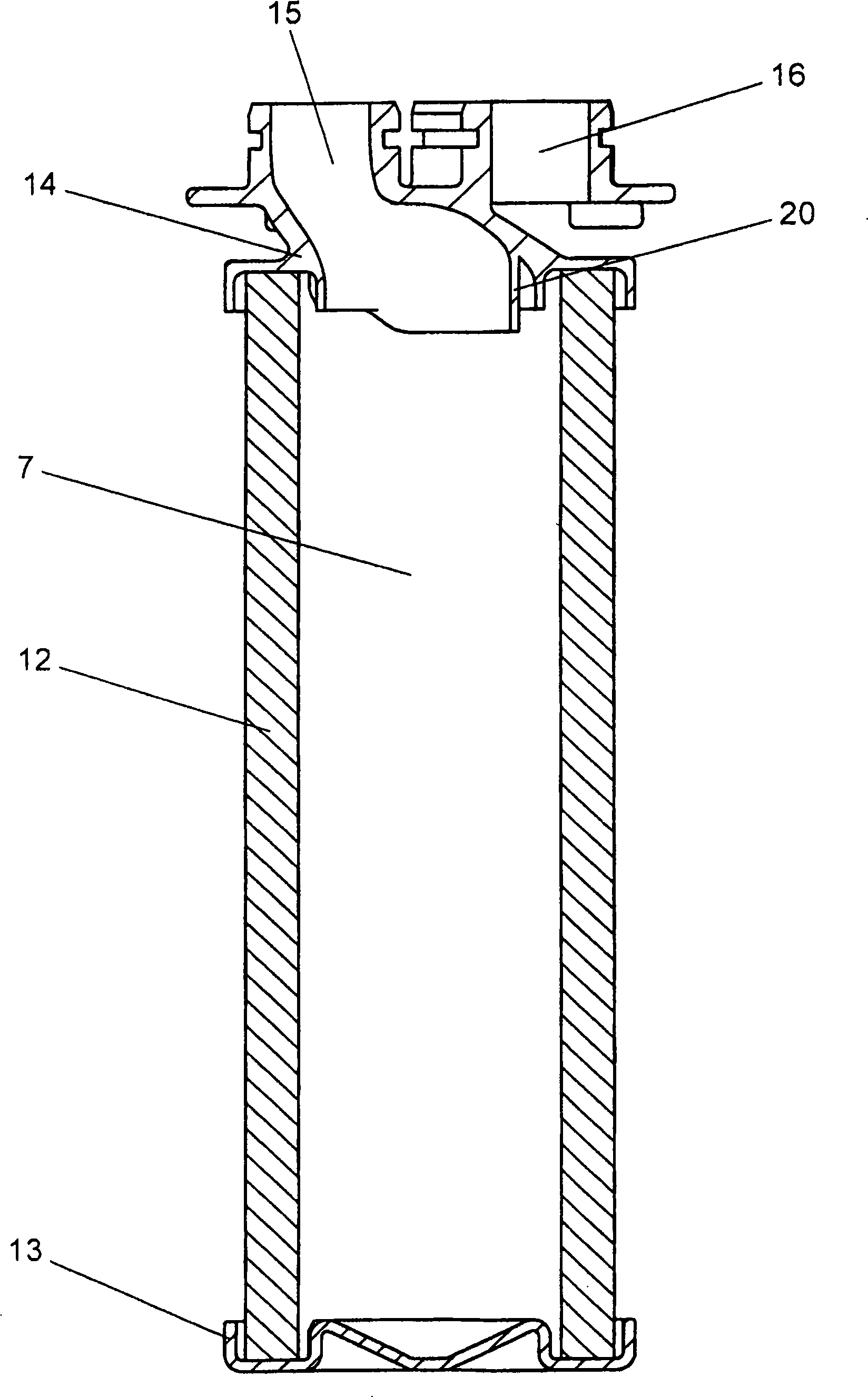
[0037] In addition to the two connecting flanges 3, 4 for integrating the filter into an existing compressed air system, the filter top 1 comprises an inlet channel 5 and an outlet channel 6 for connecting the connecting flanges 3, 4 to the cylinder The inner space of the shaped filter element 7 is connected to an annular (filter or collector) cavity defined by the outer surface of the filter element 7 and the inner surface of the hollow cylindrical filter bottom 2.

[0038] The filter top 1 has a pressure-resistant aluminum housing 8 in which an insert 9 made of plastic and comprising inlet and outlet channels 5 , 6 is arranged. In addition to the inlet and outlet channels 5 , 6 , this insert of the filter top 1 has a sensor 10 for differential pressure indication (not shown), mounted replaceably in a bore of the insert 9 .

[0039] The d...


PUM


Abstract

The invention relates to a filter, in particular for pressurised gas systems, comprising an upper filter part with at least one inlet channel and at least one outlet channel and a lower filter part with a filter element. According to the invention, the upper filter part has a pressure-resistant housing and an insert, in which the course of the inlet and outlet channels is optimised.

Description

technical field [0001] This invention relates to filters, and more particularly to filters for compressed gas and compressed air systems. Background technique [0002] Compressed gas systems, especially compressed air systems, require filters to separate solid and liquid foreign objects such as dirt particles, condensate and oil entrained in the gas stream. [0003] Such filters are usually made of a two-part housing with a top and a bottom, which are bolted or snapped to each other by connecting bolts or snap-fit ​​joints. The housing top typically has inlet and outlet channels on diametrically opposite sides. The inlet channel either enters centrally into a hollow cylindrical filter element arranged at the bottom, or into an annular space between the filter element and the bottom housing. As a result, the outlet channel extends either from the annulus, or from the inside of the filter element, depending on whether the flow through the filter element is from the inside to...

Claims


Application Information

Patent Timeline
Patent Type & Authority Applications(China)
IPC IPC(8): B01D46/24
CPCB01D46/0004B01D46/446B01D46/0039B01D46/2414Y10S55/17B01D46/00B01D46/24
Inventor H-M·舒斯特J·舍费尔A·瑞贝蒂P·格罗特
Owner DONALDSON FILTRATION DEUT GMBH
Learn More