
Modular radiation beam analyzer

A radiation beam and analyzer technology, applied in the field of modular radiation beam analyzers, can solve problems such as long initial start-up time

Inactive Publication Date: 2009-07-08
丹尼尔纳瓦罗
View PDF8 Cites 9 Cited by
  • Summary
  • Abstract
  • Description
  • Claims
  • Application Information

AI Technical Summary

Problems solved by technology

The Wellhofer device utilizes a toothed belt and motor combination to move the probe through the water, requiring a long initial start-up time

Method used


Image

  • Modular radiation beam analyzer
  • Modular radiation beam analyzer
  • Modular radiation beam analyzer

Examples


Embodiment Construction

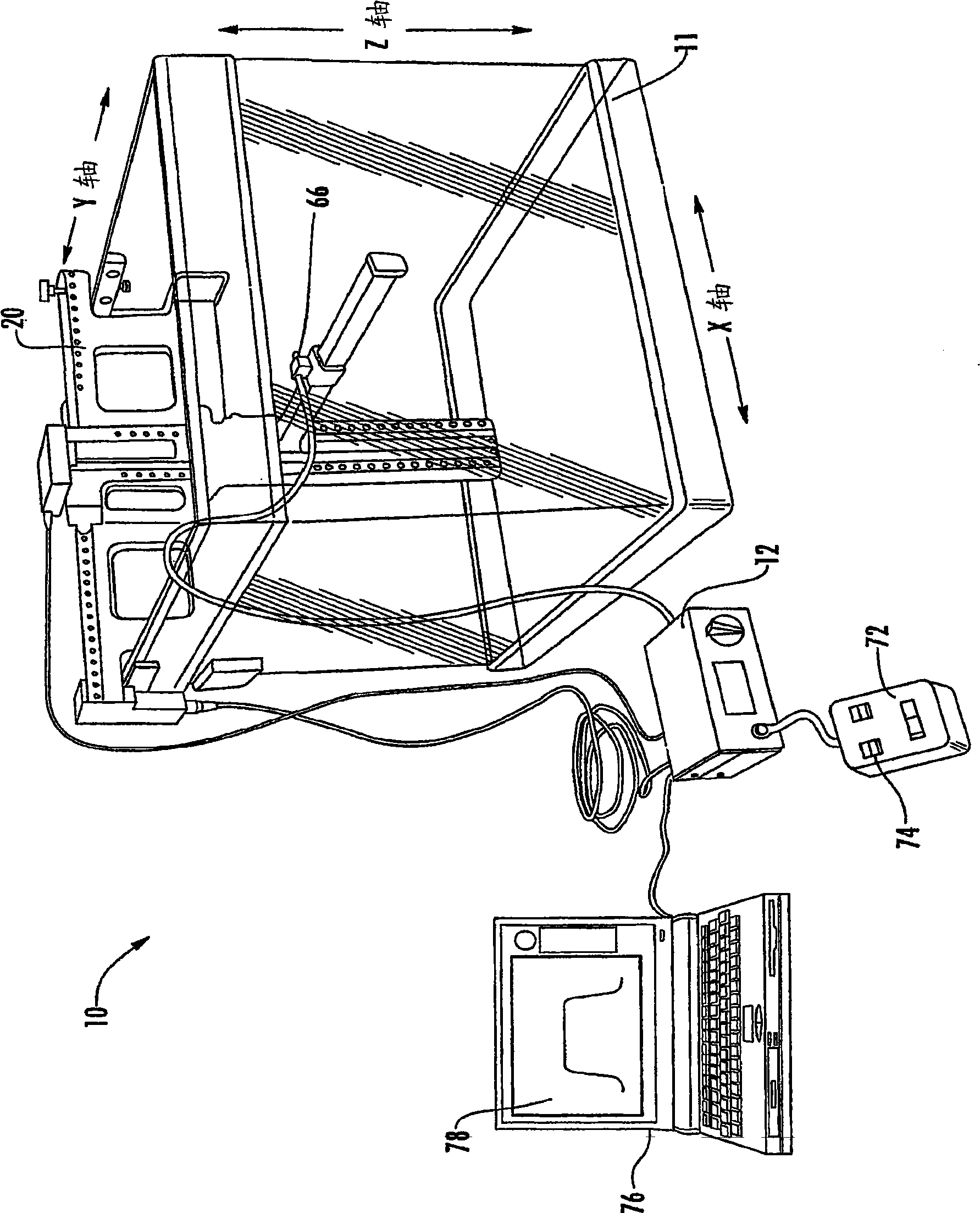
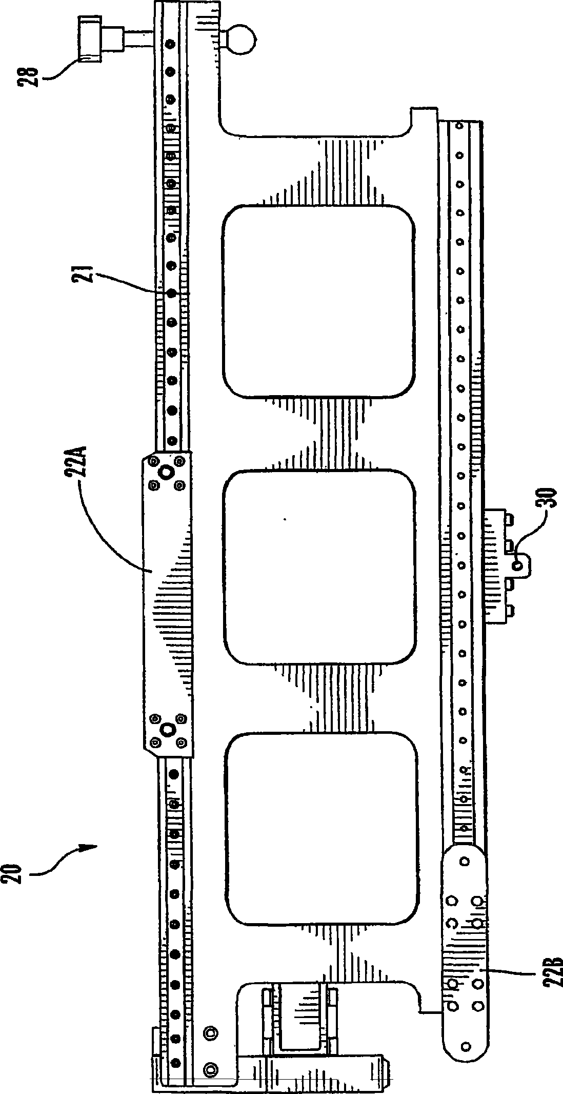
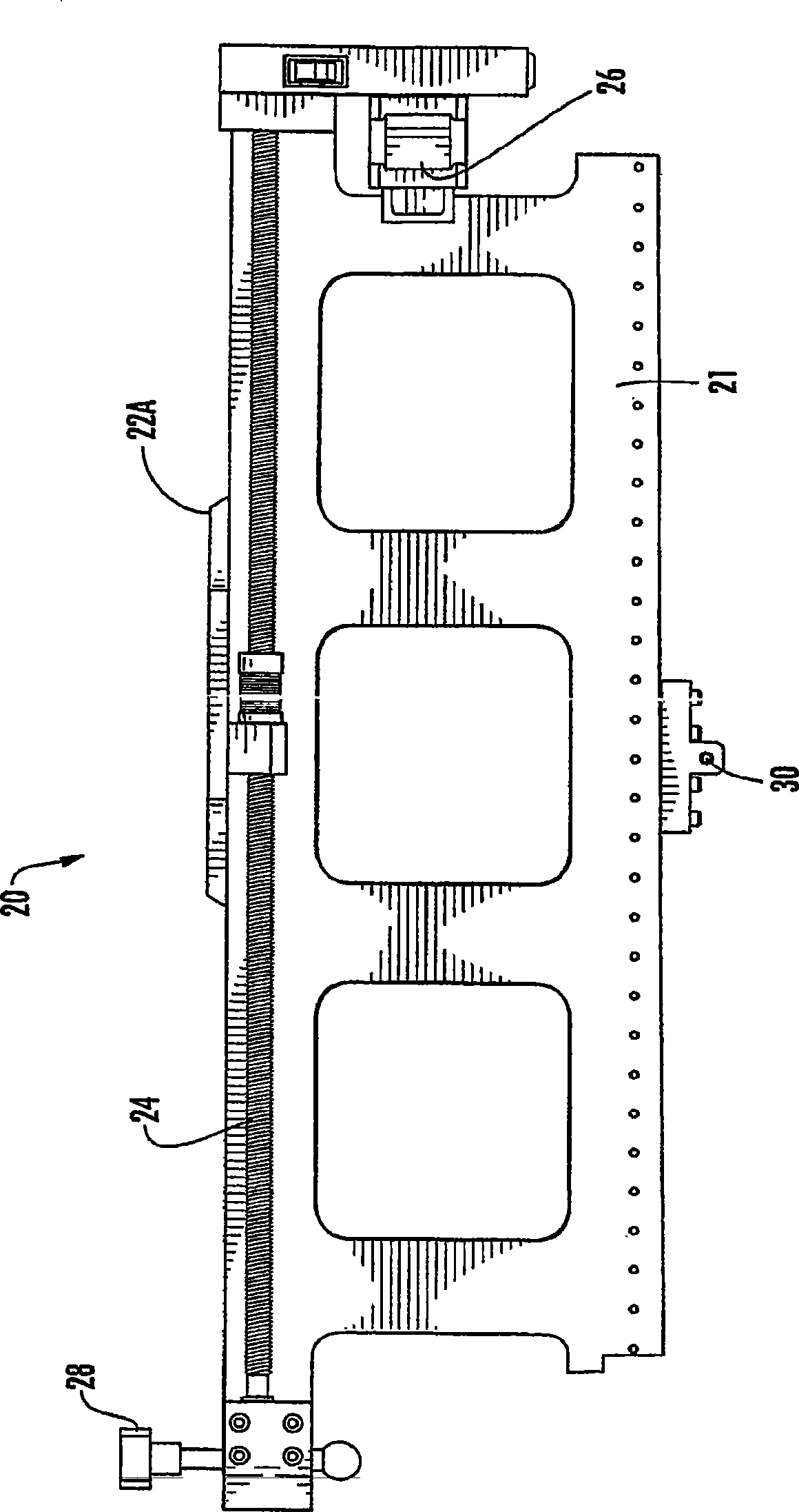
[0049] see figure 1 with 14 , illustrates a modular radiation beam analyzer 10 for measuring the distribution and intensity of radiation produced by a radiation source. The radiation beam analyzer 10 generally includes a phantom case 11 constructed and arranged to contain a material having a density close to that of a human body. Typically, the phantom box is sized to accommodate the X-axis module 20, the Y-axis module 60 and the Z-axis module 32 of the radiation beam analyzer. The bottom and walls of the box may be constructed of acrylic or other suitable material. When filled with water, the tank 11 acts as a water phantom simulating the patient's body under radiation treatment. The individual X-axis, Y-axis and Z-axis modules are constructed and arranged to fit neatly within a conveniently portable carry case 102 . Each axis is also constructed and arranged to operate independently of the other axes. In this way, a desired number of shafts can be quickly fitted togethe...


PUM


Abstract

The instant invention is a modular radiation beam analyzer for measuring the distribution and intensity of radiation produced by a radiation source. specifically, the instant invention is a modular radiation scanning device that includes up to three modules. By selecting and assembling a predetermined number of modules a radiation detector may be manipulated through up to three axes for radiation beam scans as well as direct Tissue Maximum Ratio (TMR) and / or Tissue Phantom Ratio (TPR) scans.

Description

technical field [0001] The present invention relates to a method and apparatus for measuring radiation dose at a target from a linear accelerator or other radiation generating device, and more particularly to the use of a movable radiation detector, usually an ionization chamber. Background technique [0002] Various known medical techniques for the treatment of malignancies involve the use of radiation. Radiation sources (eg, medical linear accelerators) are commonly used to produce radiation to specific target regions of a patient's body. It is extremely important to use proper dosimetry to ensure that the proper radiation dose is applied to the malignant tumor area. When radiation is applied, the radiation produces an ionizing effect on the malignant tumor tissue, thereby destroying the malignant tumor cells. As long as the dosimetry of the radiation applied is properly monitored, malignant tumors can be treated without damaging surrounding healthy tissue. Accelerators...

Claims


Application Information

Patent Timeline
Patent Type & Authority Applications(China)
IPC IPC(8): G02B6/36
CPCA61N2005/1076G01T1/169
Inventor 丹尼尔·纳瓦罗
Owner 丹尼尔纳瓦罗
Learn More