High-position braking lamp control system with graded illumination function and its control method

A technology for high-position brake lights and control systems, which is applied to components of lighting devices, lighting and heating equipment, transportation and packaging, etc. Reliable and practical effect

Inactive Publication Date: 2009-07-15
CHERY AUTOMOBILE CO LTD
View PDF0 Cites 14 Cited by
  • Summary
  • Abstract
  • Description
  • Claims
  • Application Information

AI Technical Summary

Problems solved by technology

This control method needs to add a travel switch to the traditional braking system, which increases the

Method used


Image

  • High-position braking lamp control system with graded illumination function and its control method
  • High-position braking lamp control system with graded illumination function and its control method
  • High-position braking lamp control system with graded illumination function and its control method

Examples


Embodiment Construction

[0029] The present invention will be further described below in conjunction with the accompanying drawings.

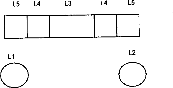
[0030] The high-mounted brake lights are composed of LED lights connected in parallel, divided into three groups, and illuminated in stages according to the braking situation. During the braking process, due to different braking methods, the braking deceleration of the vehicle is also different. The control part 1 collects the signal of the brake switch and the signal of the braking deceleration of the vehicle, and then lights up the brake lights in stages according to the state of the brake switch and the braking deceleration. The specific grouping conditions are as follows: image 3 shown.

[0031] The brake lights are switched on in three stages depending on the braking deceleration. In general, when the braking deceleration of the vehicle is 0.2g~0.5g, it is the deceleration when ordinary users encounter red lights and other situations; when it is 0.5g~0.7g, it is...


PUM


Abstract

The invention discloses a high-mount brake lamp control system and a control method thereof. The control system comprises three groups of high-mount brake lamps, a control part and a deceleration sensor; wherein, the first high-mount brake lamp group and two common brake lamps are controlled by a brake switch and lit at the moment when the brake pedal is trod; the second high-mount brake lamp group is co-controlled by a brake switch and a brake deceleration, and lit when the brake deceleration ranges from 0.2g to 0.5g after the brake pedal is trod; the third high-mount brake lamp group is also co-controlled by a brake switch and a brake deceleration, and lit when the brake deceleration is greater than 0.5g after the brake pedal is trod. The system can lighten the high-mount brake lamps by grades according to the brake situation of vehicles, thus the brake situation of front vehicles can be fed back to the driver of the rear vehicle and the driver can take proper measures to avoid the rear-end collision according to the lightening situation of the brake lamps.

Description

technical field [0001] The invention relates to a control system capable of stepping on brake lamps according to vehicle braking conditions. Background technique [0002] The brake lights used in cars in the past, no matter what kind of braking method (ordinary braking or emergency braking) the driver uses, and how much the braking deceleration is, the brake lights are all lit at the same time. Therefore, the driver of the vehicle behind cannot judge whether the front vehicle is decelerating or slamming the brakes according to the lighting situation of the brake light. Like this, because the driver of the rear car cannot understand the braking situation of the vehicle in front in time, it cannot take appropriate measures in time, and rear-end collision accidents are very prone to occur. This situation is more obvious when the vehicle is running on the expressway. In order to reflect the speed of automobile braking and make the following drivers make correct responses in tim...

Claims


Application Information

Patent Timeline
IPC IPC(8): F21S8/10F21V23/00B60Q1/44F21W101/14
Inventor 唐风敏
Owner CHERY AUTOMOBILE CO LTD
Why Eureka
Try Eureka