Production apparatus for lamp holder and lamp filament component of highly efficient multi-position continuous lamp

A multi-station, filament technology, applied in the direction of electrical components, lead-in wires, luminous bodies, etc., can solve the problems of restricting production efficiency and manpower consumption, and achieve the effects of manpower saving, high production efficiency and stable product quality

Inactive Publication Date: 2009-07-15
李家凌
View PDF1 Cites 10 Cited by
  • Summary
  • Abstract
  • Description
  • Claims
  • Application Information

AI Technical Summary

Problems solved by technology

[0002] The existing multi-station continuous electric lamp cap filament component production device, as disclosed in patent application 200710092753. Filament foot clamping mechanism next to the turntable, molybdenum sheet welding mechanism, tantalum sheet welding mechanism, filament welding mechanism, filament member unloading mechanism, power transmission device that drives the turntable to rotate, control power transmission device, filament foot clamping mechanism, molybdenum sheet The welding mechanism, the tantalum sheet welding mechanism, the filament welding me

Method used


Image

  • Production apparatus for lamp holder and lamp filament component of highly efficient multi-position continuous lamp
  • Production apparatus for lamp holder and lamp filament component of highly efficient multi-position continuous lamp
  • Production apparatus for lamp holder and lamp filament component of highly efficient multi-position continuous lamp

Examples


Embodiment Construction

[0012] Now in conjunction with accompanying drawing and embodiment the present invention is described in further detail:

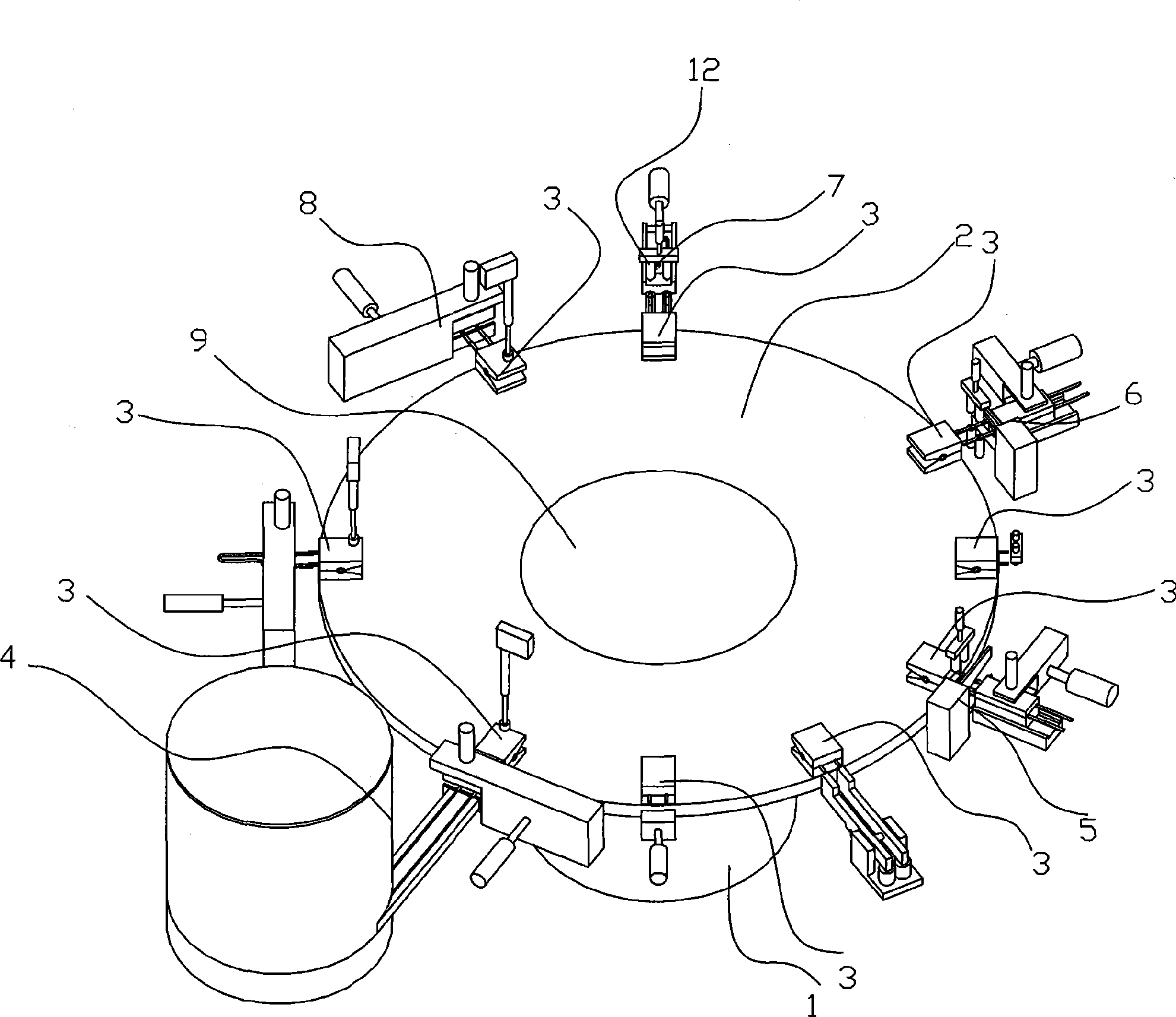
[0013] like figure 1 As shown, the present invention includes a frame 1, a turntable 2 arranged on the frame 1, a filament foot clip 3 arranged on the turntable 2, a filament foot clamping mechanism 4 distributed next to the turntable 2, and a molybdenum sheet welding mechanism. 5. Tantalum sheet welding mechanism 6. Filament welding mechanism 7. Filament member unloading mechanism 8. Power transmission device that drives turntable 2 to rotate 9. Control power transmission device 9. Filament foot clamping mechanism 4. Molybdenum sheet welding mechanism 5. Tantalum The sheet welding mechanism 6, the filament welding mechanism 7, the filament member blanking mechanism 8, the electronic control device 10 that operates according to the program, and some detection devices 19 connected with the electronic control device to detect whether the filament foot parts ...


PUM


Abstract

A high efficiency multi-station continuous electric lamp base filament element production device comprises a machine frame, a rotary table rotationally arranged on the machine frame, a filament foot clip arranged on the rotary table, a filament foot up-clip mechanism, a molybdenum sheet welding mechanism, a tantalum sheet welding mechanism, a filament welding mechanism and a filament element unloading mechanism distributed beside the rotary table in turn, a power transmitting means driving the rotary table rotation, an electronic control apparatus for controlling the power transmitting means, the filament foot up-clip mechanism, the molybdenum sheet welding mechanism, the tantalum sheet welding mechanism, the filament welding mechanism and the filament element unloading mechanism to operate according to the program, which is characterized in that the filament welding mechanism comprises a filament automatic up-clip mechanism and a welding mechanism. The invention has advantages of high production efficiency, saving labor and stable product quality comparing to the prior art.

Description

Technical field: [0001] The invention relates to a production device of an electric light source component. Background technique: [0002] The existing multi-station continuous electric lamp cap filament component production device is as disclosed in the patent application 200710092753. Filament foot clamping mechanism next to the turntable, molybdenum sheet welding mechanism, tantalum sheet welding mechanism, filament welding mechanism, filament member unloading mechanism, power transmission device that drives the turntable to rotate, control power transmission device, filament foot clamping mechanism, molybdenum sheet The welding mechanism, the tantalum sheet welding mechanism, the filament welding mechanism, and the filament member unloading mechanism are composed of an electronic control device that operates according to a program. Compared with the previous technology, although the production efficiency of this device has been greatly improved, the filament It also nee...

Claims


Application Information

Patent Timeline
IPC IPC(8): H01K3/04H01K1/16H01K1/40
Inventor 李家凌
Owner 李家凌
Why Eureka
Try Eureka