Cloth tensioning apparatus in embroidering machine

A tensioning device, embroidery machine technology, applied in the direction of the embroidery machine mechanism, embroidery machine, feeding device, etc., can solve the problems of differences, damage to product value, difficulties, etc., and achieve high-quality results

Inactive Publication Date: 2009-07-15
金台基
View PDF0 Cites 15 Cited by
  • Summary
  • Abstract
  • Description
  • Claims
  • Application Information

AI Technical Summary

Problems solved by technology

However, the longer the length of the tenter, the greater the damage to the cloth by the needle bar, which leads to deterioration of sales force
In addition, in the state where the cloth is rolled up, there is a problem that only a part of the cloth that is in contact with the tenter is stretched
This makes it difficult to continuously apply proper tension in the X-axis direction of the cl

Method used


Image

  • Cloth tensioning apparatus in embroidering machine
  • Cloth tensioning apparatus in embroidering machine
  • Cloth tensioning apparatus in embroidering machine

Examples


Embodiment Construction

[0016] Reference will now be made in detail to the preferred embodiments of the invention, examples of which are illustrated in the accompanying drawings. Wherever possible, the same reference numbers will be used throughout the drawings to refer to the same or like parts. In the following description, in order to facilitate a better understanding of the present invention, detailed descriptions of known prior technologies or functions will be omitted.

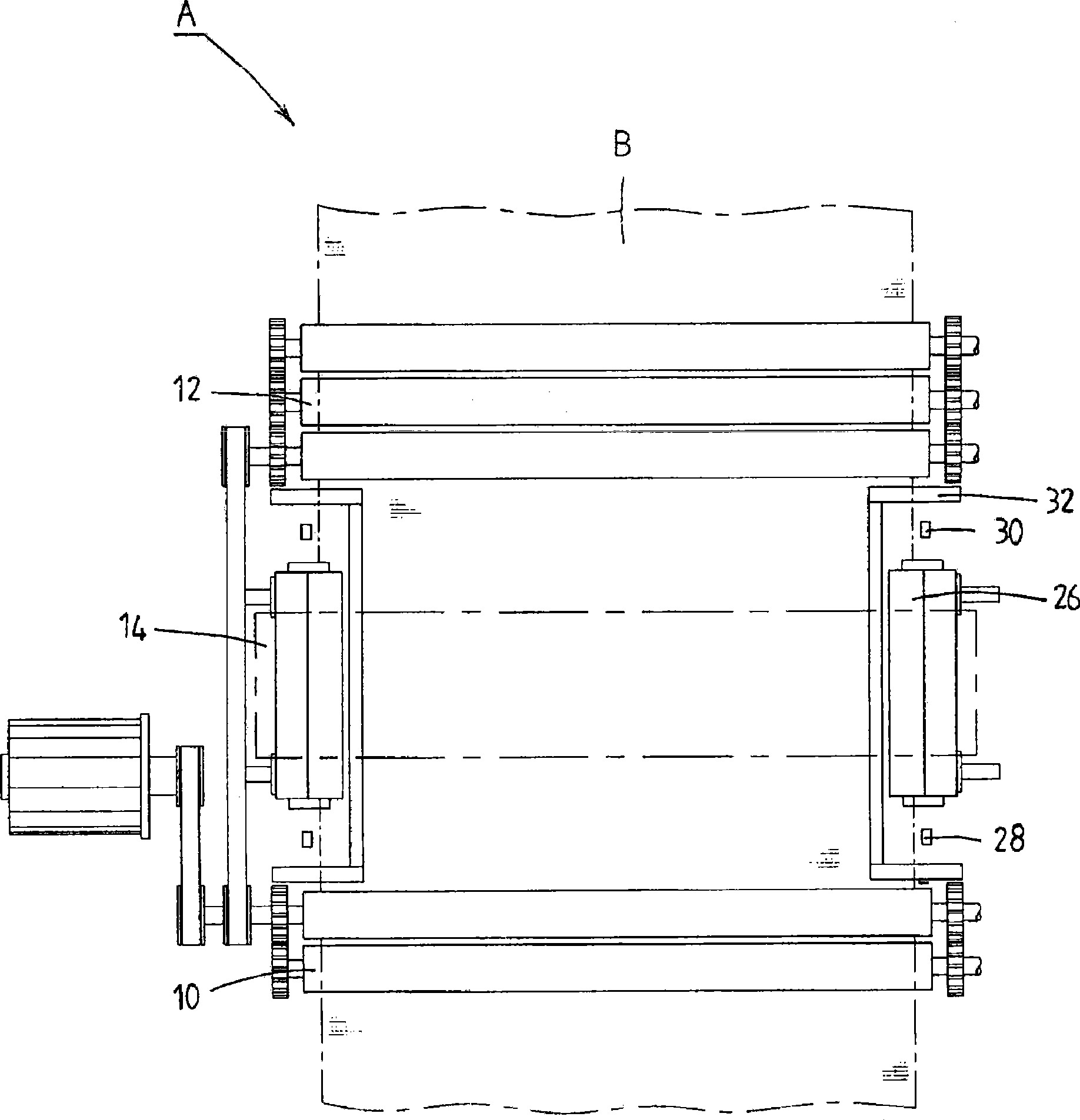
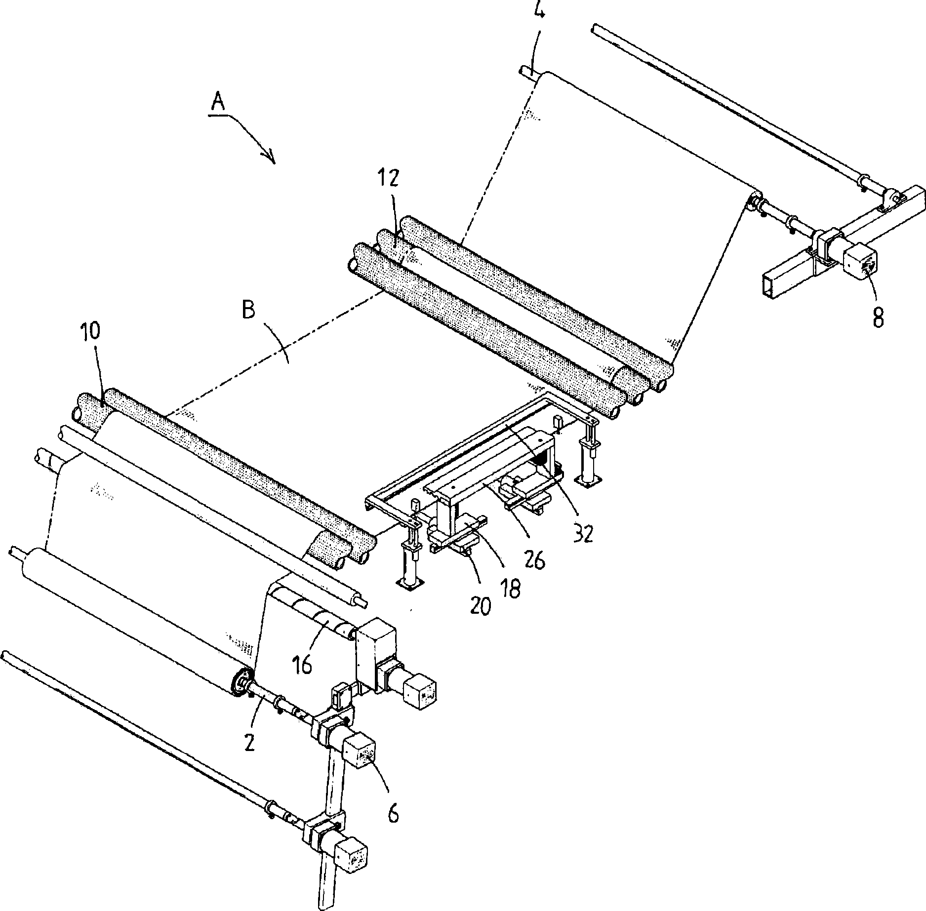
[0017] figure 1 and figure 2 These are a plan view and a perspective view illustrating an embroidery machine according to the present invention, respectively. Such as figure 1 and figure 2 As shown, the embroidery machine A includes a cloth supply roller 2, a cloth winding roller 4, torque motors 6 and 8 and a head 14, and the torque motors 6 and 8 are used to rotate the cloth supply roller 2 and the cloth winding roller 4 respectively, The head 14 is disposed between the front delivery roller 10 and the rear delivery ro...


PUM


Abstract

Disclosed is a cloth tensioning apparatus in an embroidering machine (A), which includes nipper units (26) to be moved forward and rearward and leftward and rightward by LM guides (18, 20), sensors (28, 30) for determining a forward and rearward movement distance of the nipper units (26), and pressure members (32) having pressure portions (32a) located inside the nipper units (26). Thereby, an embroidering operation is performed in a state wherein the nipper units (26) seize the cloth (B) while continuously applying a tension in an X-axis direction of the cloth (B). The embroidering operation is temporarily stopped if the nipper units (26) are deflected forward, and the nipper units (26) are returned in a state wherein the cloth (B) is tensioned by the pressure members (32). The nipper units (26) are again operated to seize the cloth (B) at their returned positions. As a result, a constant tension is continuously applied even in the X-axis direction of the cloth (B) during the embroidering operation.

Description

technical field [0001] The present invention relates to a cloth tensioning device in an embroidery machine, and more particularly, to a cloth tensioning device capable of continuously applying a constant tension to the cloth even in the X-axis direction of the cloth. Background technique [0002] The inventors of the present invention have developed various embroidery machines, such as the embroidery machine disclosed in Korean Utility Model Registration No. 223005, in which the head can be displaced in the X-axis direction of the cloth to perform embroidery work, And an embroidery machine disclosed in Korean Laid-Open Patent No. 2005-0111523, in which a tension force is applied in both the X-axis direction and the Y-axis direction of the cloth during embroidery work. [0003] Specifically, in the aforementioned Korean Laid-Open Patent No. 2005-0111523, it is arranged that a torque motor which rotates the cloth supply roller and the cloth winding roller continuously applies ...

Claims


Application Information

Patent Timeline
IPC IPC(8): D05C9/12
CPCD05C9/12
Inventor 金台基李相馥金济捀鲁锡洪
Owner 金台基
Why Eureka
Try Eureka