Pipe connector

A technology for pipe joints and connecting pipes, which is applied in the field of pipe joints, can solve the problems of high manufacturing cost, complex structure, and difficult promotion, and achieve the effect of low cost, compact structure, and quick installation and disassembly

Active Publication Date: 2010-10-06
佛山市立联吉管业科技有限公司
View PDF0 Cites 0 Cited by
  • Summary
  • Abstract
  • Description
  • Claims
  • Application Information

AI Technical Summary

Problems solved by technology

[0003] With the development of technology, the connection method of using internal tooth locking ring instead of thread to lock the pipe has appeared on the market, but the structure of the existing series of push-fit connection pipe fittings is too complicated, resulting in high manufacturing costs, so it has been difficult to use in the world Promotion within the scope

Method used


Image

  • Pipe connector
  • Pipe connector
  • Pipe connector

Examples


Embodiment Construction

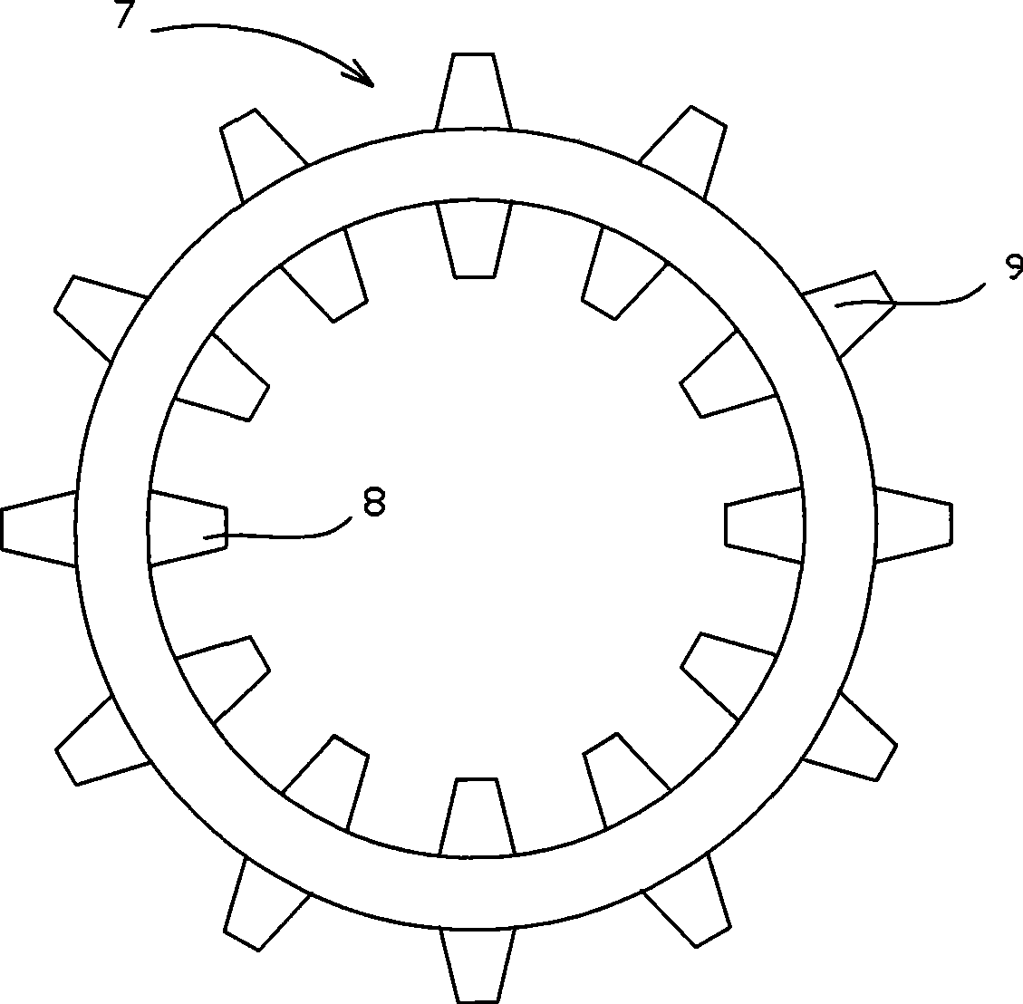
[0044] Figure 19 yes Figure 18 top view diagram.

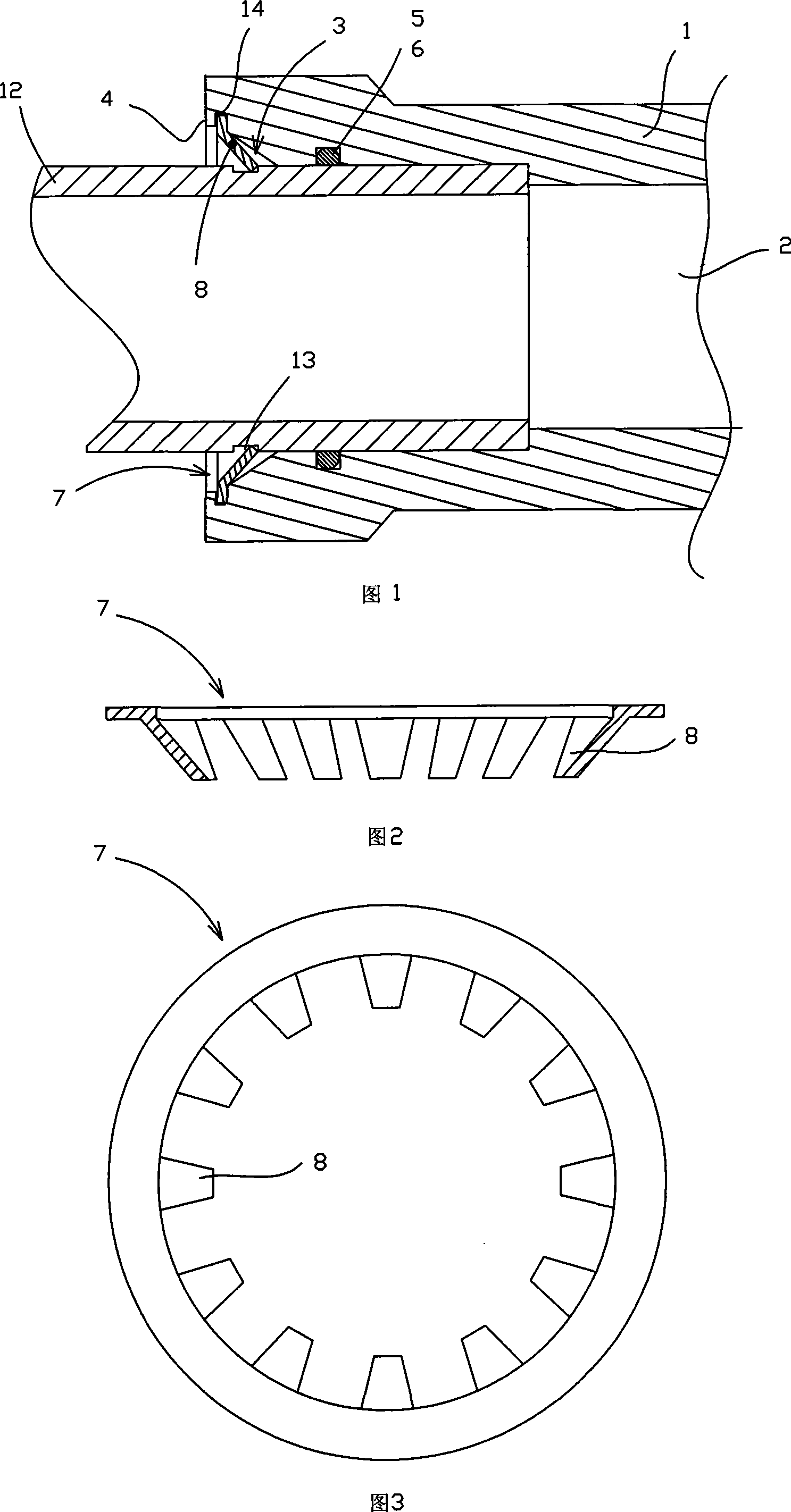
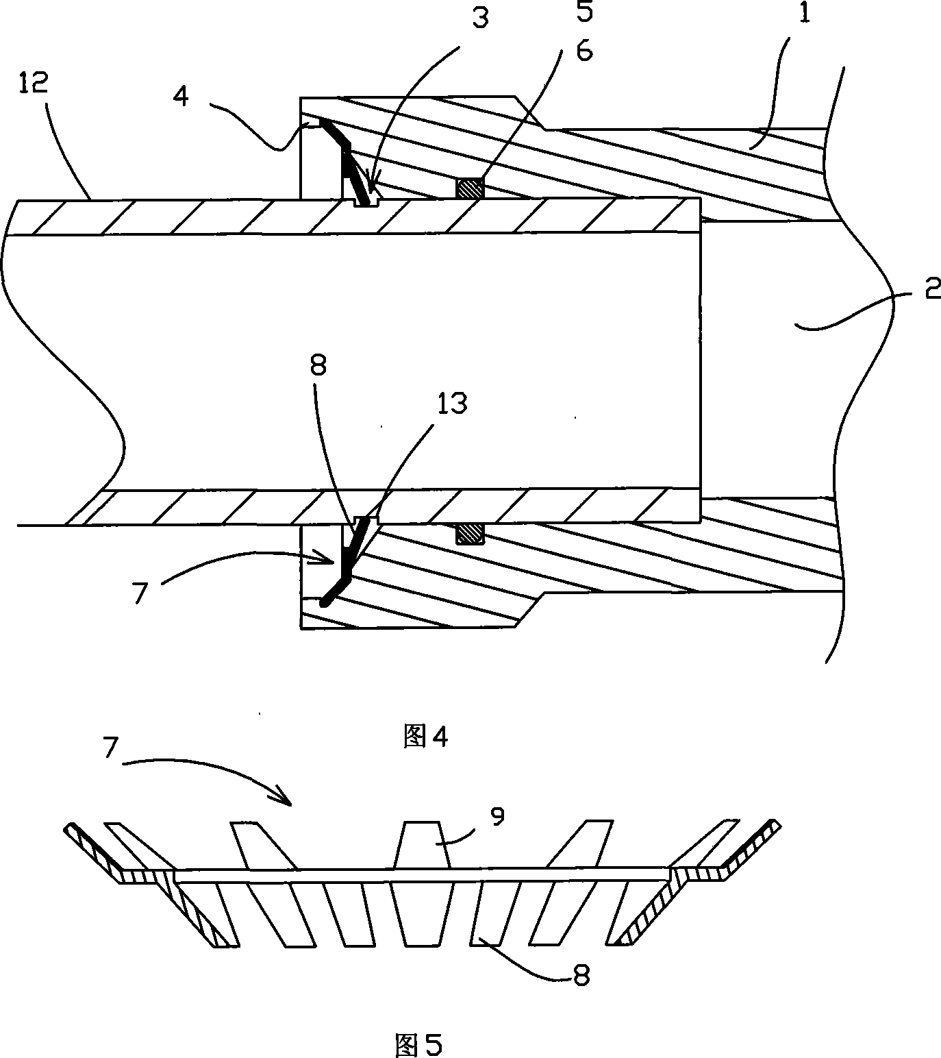
[0045] In the figure: 1-joint body, 2-through hole, 3-flare mouth, 4-protruding ring or bump, 5-apron groove, 6-sealing rubber ring, 7-elastic locking gear ring, 8-inner Folding teeth, 9-fixed teeth, 10-gap of the elastic locking gear ring, 11-ring hole, 12-connected pipe, 13-outer clamping pipe groove of the connected pipe, 14-positioning groove.

[0046] like Figure 1 to Figure 3 The shown pipe joint embodiment 1 includes a joint body 1 with a through hole 2. There is a positioning step in the middle of the through hole 2 for the positioning of the connected pipe 12. On the inner wall of the through hole 2, there is a rubber ring groove 5 equipped with a seal. The rubber ring 6 is used to ensure the sealing between the connected pipe and the pipe joint; the two ports of the through hole 2 are the bell mouth 3, and the outer end of the bell mouth is connected with a counterbore, and the bell mouth 3 is equipped with an ...


PUM


Abstract

A tube union comprises an adapter body (1) opened with a through hole (2). The middle of the through hole is provided with a locating step used for locating a connected pipe (12). The inner wall of the through hole is opened with a cushion rubber socket (5) and provided with an O-ring seal (6). Two ports of the through hole are pipe sockets (3) which are internally provided with an elastic locking gear ring (7) taking the shape of a ring. The inner edge of the ring body is provided with at least two latches which blends inward in the same direction and extends out. And the outer edge of the ring body is evenly distributed with fixed teeth which bends outward in the same direction and extends out; the stretching direction of the fixed teeth runs counter to an infolding latch. The hole wallat the most external end of the pipe sockets is provided with a bulge loop (4) and at least two projections; or the hole wall at the most external end of the pipe sockets is opened with a locating groove (14); the inflexed latch extends out and is blocked in the socket of the connected pipe and prevent the connected pipe from withdrawing from the tube union. The tube union has few fittings, simple structure and low cost and can be quickly arranged and dismantled by a special tool which is separately designed and independent of tube unions.

Description

technical field [0001] The invention relates to a pipe joint, in particular to a quick pipe joint. Background technique [0002] Traditional metal pipe connections are mainly threaded or welded. Threaded connections must be threaded on the pipe wall, which causes 40% of the material waste of the pipe wall thickness and weakens the strength of the pipe. Welding requires that the pipe has sufficient wall thickness. [0003] With the development of technology, the connection method of using internal tooth locking ring instead of thread to lock the pipe has appeared on the market, but the structure of the existing series of push-fit connection pipe fittings is too complicated, resulting in high manufacturing costs, so it has been difficult to use in the world promotion within the scope. Contents of the invention [0004] Aiming at the deficiencies of the prior art, the technical problem to be solved by the present invention is to provide a pipe joint with few parts, simple a...

Claims


Application Information

Patent Timeline
Patent Type & Authority Patents(China)
IPC IPC(8): F16L37/091
Inventor 伍婧绫王华华
Owner 佛山市立联吉管业科技有限公司
Why Eureka
Try Eureka