
Lens system suitable for LED road lamp

A technology of LED street lamps and lens systems, which is applied in the direction of condenser mirrors, components of lighting devices, semiconductor devices of light-emitting elements, etc.

Active Publication Date: 2010-06-02
NINGBO LIAOYUAN IND
View PDF5 Cites 3 Cited by
  • Summary
  • Abstract
  • Description
  • Claims
  • Application Information

AI Technical Summary

Problems solved by technology

[0005] The purpose of the present invention is to overcome the defects existing in the existing LED street lamp lens, and provide a lens system suitable for LED street lamps with a new structure. The illuminance distribution is similar to a rectangle and the illuminance is uniform, so it is more suitable for practical use and has industrial utilization value

Method used


Image

  • Lens system suitable for LED road lamp
  • Lens system suitable for LED road lamp
  • Lens system suitable for LED road lamp

Examples


no. 1 example

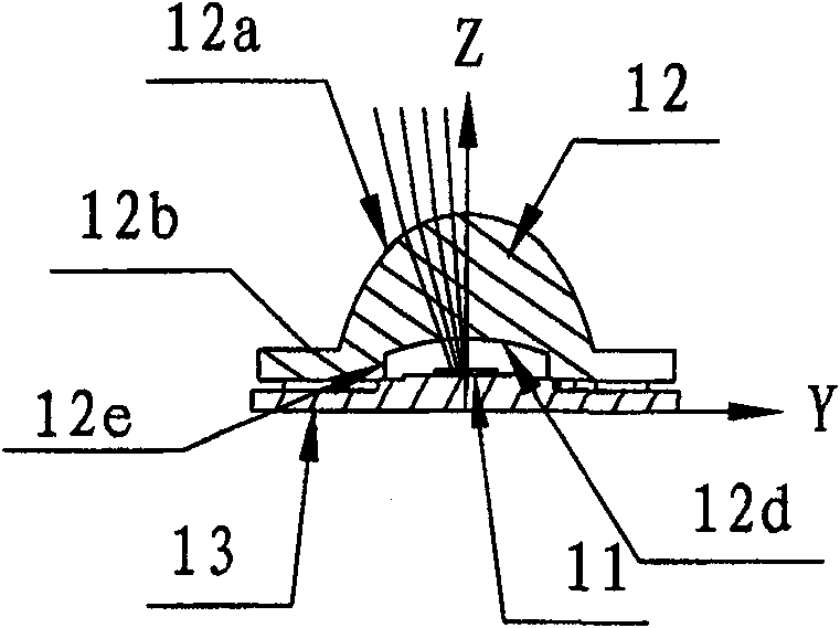
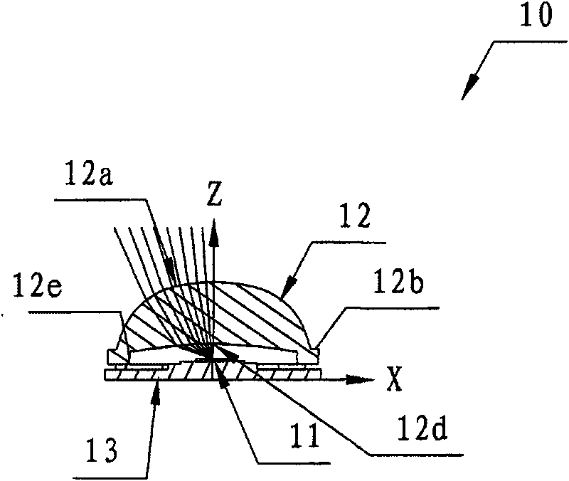
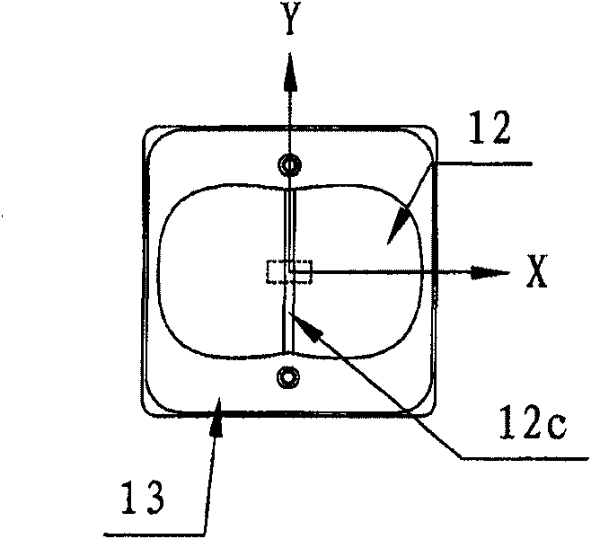
[0082] see Figure 1a-1c As shown, the lens system suitable for LED street lamps according to the first preferred embodiment of the present invention is a wide-beam lens system 10, which is mainly composed of at least one LED illuminant 11 and a lens 12, and the edge of the lens is fixed on the On the mounting board 13 of the LED illuminant 11, the lens 12 is composed of an incident surface 12d, a light-emitting surface 12a, an outer lens edge surface 12b, an inner lens edge surface 12e and a transition curved surface 12c.

[0083] The focal point of the incident surface 12d of the lens 12 is near the center of the LED luminous body 11, the wrap angle of 1 / 10 peak light intensity of the LED luminous body 11 is 170°, and the direction of the optical axis of the LED luminous body 11 is the central axis of the lens 12, which is All the light emitted by the LED illuminant 11 hits the incident surface. At the same time, since the loss of light through the medium is related to the in...

no. 2 example

[0085] like Figure 2a-2c As shown, the second preferred embodiment of the present invention is a lens system suitable for LED street lamps, which is a narrow beam lens system 20, mainly composed of at least one LED illuminant 21 and a lens 22, and the edge of the lens is fixed on the On the mounting plate 23 of the LED illuminant 11, the lens 22 is composed of an incident surface 22d, a light emitting surface 22a, an outer lens edge surface 22b, an inner lens edge surface 22e and a transition curved surface 22c. The wrap angle of the concave curved surface 22d of the incident surface of the lens is appropriately reduced, and the wrap angle of the light exit surface 22a is also adjusted accordingly. At the same time, the curvature of the convex surface is appropriately increased, and the light passes through the lens and is refracted by the light exit surface 22a to form an X-axis direction of 50°-60° , the Y-axis direction is 20°-30°, which is close to a rectangular spot. Suc...

no. 3 example

[0087] like Figures 3a-3c As shown, the third preferred embodiment of the present invention is a lens system suitable for LED street lamps, which is a medium beam lens system 30, mainly composed of at least one LED illuminant 31 and a lens 32, and the edge of the lens is fixed on the On the mounting board 33 of the LED illuminant 11, the lens 32 is composed of an incident surface 32d, a light emitting surface 32a, an outer lens edge surface 32b, an inner lens edge surface 32e and a transition curved surface 32c. The concave surface 32d of the incident surface of the lens has a wrapping angle close to the half-peak light intensity wrapping angle of the LED illuminant, which is 120°, and the wrapping angle of the light-emitting surface 32a is within 30°, with a large curvature, and the light is concentrated in a small range to form a spotlight beam. The X-axis direction is 25°-30°, and the Y-axis direction is 10°-15°, which is close to a rectangular spot. The central light inte...


PUM


Abstract

The invention relates to a lens system which is applicable to an LED street lamp and is matched with an LED illuminant for use to form light distribution with multiple Light beam angles and light intensities. A plane of light incidence of a lens in the system being close to the LED illuminant is a compound curved surface of an aspherical concave surface, and a light-emitting surface is a compoundcurved surface of an aspherical convex surface; the shapes of the incident surface and the emitting surface are determined by the luminescent properties of the LED illuminant and the requirement of the emergent ray; after the light ray emitted by the LED illuminant is refracted by the lens, facula formed on the irradiation surface within a certain distance has the characteristics of being comparatively long in the distance covered by the facula along one direction being vertical to the axes of the LED illuminant, being comparatively shorter in the distance covered by the facula along another direction being vertical to the direction, being symmetrical in the shapes of the faculas correspondingly to the axes of the LED illuminant, and taking on the distribution which is similar to rectangle. Similar plane isolux distribution curve shape as well as completely different maximum light intensity values of the light beam and half peak value light intensity light beam wrap angles can be obtained by the LED illuminant through different lenses, so that the lens system is especially suitable for the LED light fittings having the requirement of rectangle illumination scope.

Description

technical field [0001] The invention relates to a lens of an LED lamp in the lighting field, in particular to a lens system of an LED street lamp suitable for directional lighting. It is a composite curved surface where the light incident surface of the lens close to the LED illuminant is aspherical concave surface, and the light-emitting surface is a composite curved surface with aspherical convex surface. It is suitable for LED lamps with rectangular lighting range requirements in highways and tunnels, and has become a new design with considerable practicality and progress, suitable for widespread application in the industry. Background technique [0002] At present, the lens used for the existing LED lamps is basically a condensing lens, and the light spot formed by the emitted light is a small circle or an ellipse. For example, Chinese invention patent 20071006722.X discloses a condensing lens for high-power LED lamps, which can form an elliptical or circular light spot...

Claims


Application Information

Patent Timeline
Patent Type & Authority Patents(China)
IPC IPC(8): F21V5/04F21Y101/02F21W131/103F21Y115/10
CPCF21V5/04G02B19/0061G02B27/0916G02B27/0966G02B19/0014F21Y2101/02F21W2131/103Y02B20/72F21Y2115/10
Inventor 朱伯明陈海军孙建江
Owner NINGBO LIAOYUAN IND
Learn More