
Motor internal stator and manufacturing method thereof

A manufacturing method and technology of inner stator, which are applied in the manufacture of motor generators, stator/rotor bodies, electrical components, etc., can solve the problems of torque pulsation, uneven permeability of permanent magnet air gap, difficult mechanization operation, etc. Avoid vibration and noise, improve material utilization, eliminate the effect of cogging torque

Inactive Publication Date: 2009-07-22
NINGBO POLARIS TECH
View PDF1 Cites 14 Cited by
  • Summary
  • Abstract
  • Description
  • Claims
  • Application Information

AI Technical Summary

Benefits of technology

The present inveniton describes an improved design for a machine's drive system. It uses a special type of roller called a laminate shaping plate (LSP) instead of traditional steel plates used earlier designs. This helps increase efficiency when manufacturing these components while reducing costs associated therewith. Additionally, it achieves better balance between strength and weight through stronger connections made at specific points on its surface or inside. Overall, LSP technology simplifies the process of making machines more efficient without adding extra materials like metal sheets.

Problems solved by technology

This patented technical solution described for solving issues related to current methods of assembling electric motive force generators' internal cores involves attaching fans onto each set of teeth before creation of the windings inside the machine. These processes require tools like bolting machines, riveting guns, and machining operations, making them time-consuming and expensive compared to conventional techniques.

Method used


Image

  • Motor internal stator and manufacturing method thereof
  • Motor internal stator and manufacturing method thereof
  • Motor internal stator and manufacturing method thereof

Examples


Embodiment Construction

[0031] The present invention will be further described in detail below in conjunction with the accompanying drawings and embodiments.

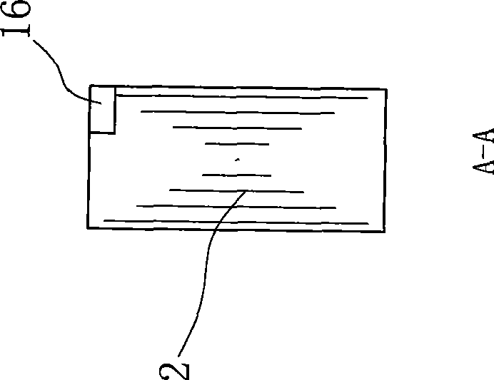
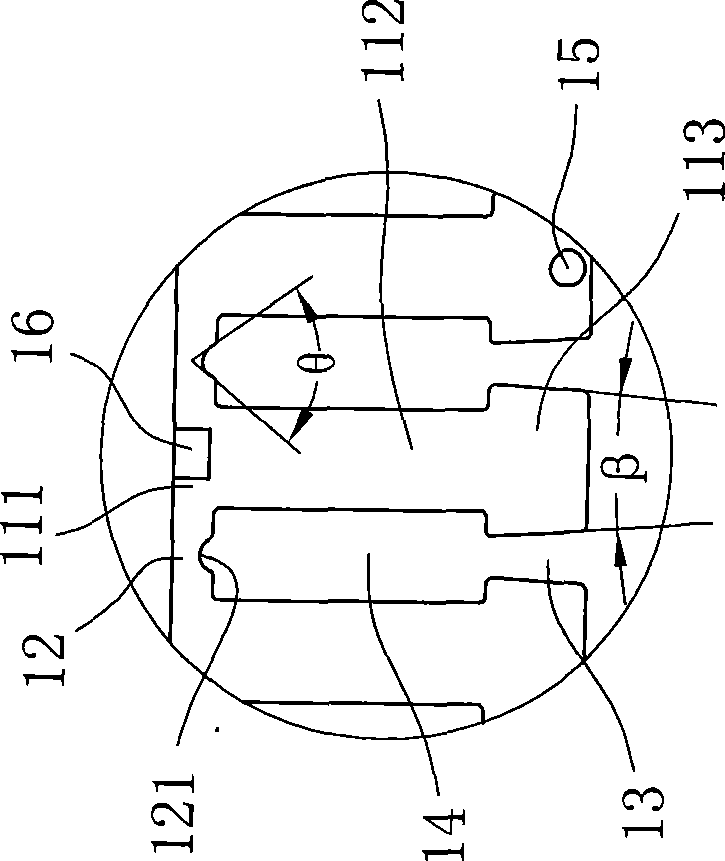
[0032] Such as Figure 1 ~ Figure 3 As shown, it is a schematic diagram of the structure of the in-line strip-shaped punches that make up the circular iron core of the present invention. The iron core is formed by winding and forming a plurality of strip-shaped punches 1 that are stamped and superimposed on each other. Each strip-shaped punch 1 includes There are multiple interconnected unit tooth blocks 11. In this embodiment, due to the large diameter of the inner stator, the formation of the iron core is not a strip-shaped punching piece that is wound and formed at one time, but is divided into three sections with the same unit Band-shaped punches 1 with the number of tooth blocks, each band-shaped punch 1 consists of 17 unit tooth blocks, two adjacent unit tooth blocks 11 are connected to each other by a connecting part 12 that can be bent...


PUM

PropertyMeasurementUnit
Diameteraaaaaaaaaa

Abstract

An inner stator of a motor comprises a plurality of iron core stamped sheets which are mutually pressed and superimposed, and take on round shapes. The inner stator is characterized in that the iron core stamped sheets are formed by winding straight line type banded stamped sheets and turning excircle, and comprise a plurality of unit tooth blocks which are connected with each other; wherein, the adjacent two unit tooth blocks are connected with each other by a connecting part, and the inner edge of which is provided with a notch which can reduce the winding stress; each of the unit tooth blocks comprises a tooth crown, a tooth body and a tooth root, a winding groove which is provided with an opening at the position of the tooth root and is communicated with the notch is arranged between every two adjacent unit tooth blocks, the tooth roots of the adjacent unit tooth blocks are abut against each other after the banded stamped sheets are wound and molded, and the winding groove forms a closed slotted hole, through which a coil can pass. Compared with the prior art, the invention improves the utilization rate of the blanking material and winding efficiency, and reduces the difficulty for designing the winding groove; as the molded iron core winding groove is closed, the tooth space torque can be eliminated, and the vibration and noise caused by overlarge torque pulsation of the motor can be avoided. The invention discloses the inner stator of the motor and a manufacturing method thereof.

Description


Claims


Application Information

Patent Timeline
Owner NINGBO POLARIS TECH
Learn More