Route bridging method, network bridge equipment and bridging network

A bridging network, bridging technology, applied in the field of network communication, can solve problems such as inability to apply

Inactive Publication Date: 2009-07-29
HUAWEI TECH CO LTD
View PDF0 Cites 23 Cited by
  • Summary
  • Abstract
  • Description
  • Claims
  • Application Information

AI Technical Summary

Problems solved by technology

However, for a VLAN-based bridged network or a provider bridged network (Provider BridgedNetwork, PBN), the bridged network internally performs data frame forwarding b

Method used


Image

  • Route bridging method, network bridge equipment and bridging network
  • Route bridging method, network bridge equipment and bridging network
  • Route bridging method, network bridge equipment and bridging network

Examples


Embodiment Construction

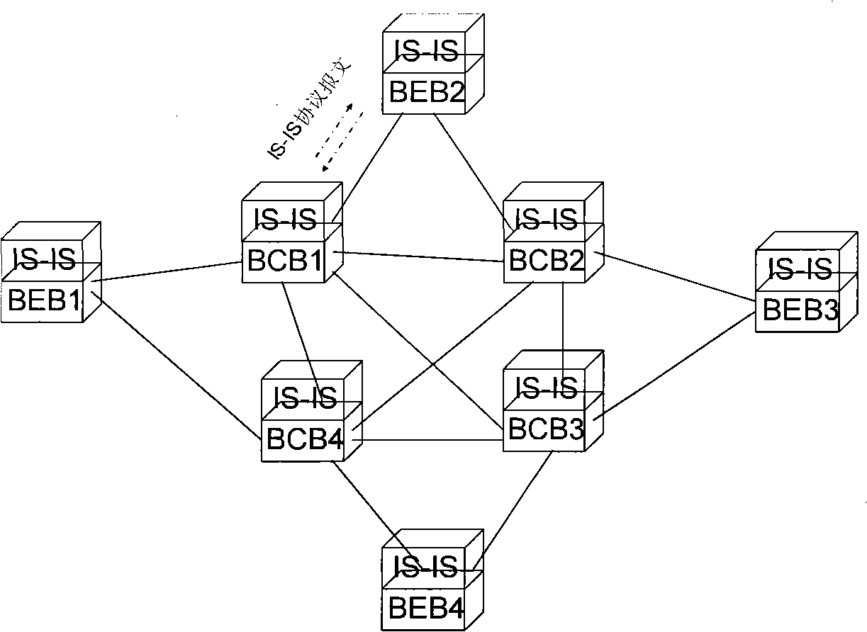
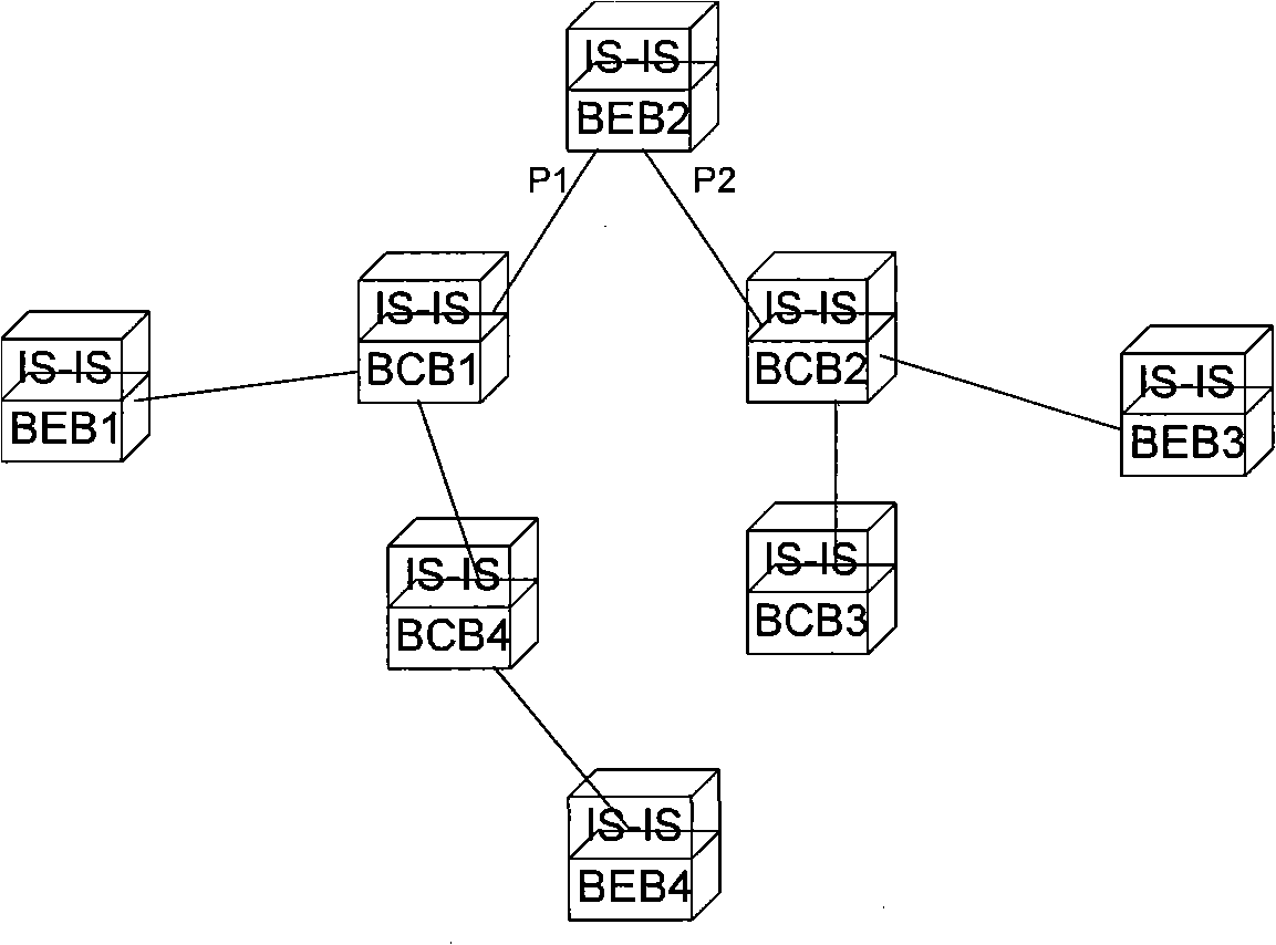
[0037]The embodiment of the present invention successfully establishes the shortest path tree topology of each node on the basis of making full use of the principle of path symmetry. Shortest path tree topology such as VLAN membership information, multicast membership information, etc. That is to say, since the egress port in one path direction is the ingress port in the opposite path direction, the root node (i.e. the first node) can determine to go out to the predetermined root node (i.e. the second node) according to the shortest path tree established by it. The outgoing port of the notification belongs to the shortest path tree topology of the predetermined root node. The root node can also determine that the incoming port of the notification belongs to the shortest path tree topology of the predetermined root node according to the notification protocol message sent by other root nodes. The root node can belong to the predetermined shortest path tree topology of the root no...


PUM


Abstract

The invention discloses a path bridging method, network bridge equipment and a bridged network. The route bridging method comprises the steps that: all nodes in the bridged network respectively calculate the shortest path tree which takes the node as a root; a first node determines an output port reaching a second node according to the shortest path tree which takes the first node as the root and is calculated by the first node, and transmits a notification protocol message through the output port so as to lead the nodes receiving the notification protocol message to acquire that an input port of the notification protocol message belongs to a shortest path tree topology which takes the second node as the root; the first node determines the input port of the notification protocol message transmitted by other nodes; the first node adds the determined output port and input port to the shortest path tree topology which takes the second node as the root; and the first node transmits data frames according to the ports contained in the shortest path tree topology which takes the second node as the root. The shortest path tree topology can be based on VLAN, and also multicast MAC address. The implementation mode perfects the shortest path bridging technology.

Description

technical field [0001] The invention relates to the technical field of network communication, in particular to a path bridging method, a network bridge device and a bridging network. Background technique [0002] The original bridged network is applicable to the local area network, and the bridge data plane establishes the forwarding table entry based on the unknown destination address data frame broadcast and the source address self-learning method. The forwarding mechanism relies on a pre-established loop-free tree network topology. Subsequently, the bridged network introduced a virtual local area network (Virtual Local Area Network, VLAN), and introduced it into the metropolitan area network, and introduced the spanning tree protocol (Spanning Tree Protocol, STP) and the rapid spanning tree protocol (Rapid Spanning Tree Protocol, RSTP), Multiple Spanning Tree Protocol (Multiple Spanning Tree Protocol, MSTP), etc., to establish a tree-shaped loop-free network topology. ...

Claims


Application Information

Patent Timeline
IPC IPC(8): H04L12/46H04L12/56H04L12/721H04L12/753
Inventor 邓柱升
Owner HUAWEI TECH CO LTD
Why Eureka
Try Eureka