
Rear part illumination apparatus of vehicle

A technology for lighting devices and vehicles, applied in vehicle parts, signal devices, bicycle accessories, etc., can solve problems such as rising costs and increasing the number of parts, and achieve the effects of ensuring sealing performance, preventing intrusion, and suppressing cost rises

Inactive Publication Date: 2009-08-05
HONDA MOTOR CO LTD
View PDF1 Cites 12 Cited by
  • Summary
  • Abstract
  • Description
  • Claims
  • Application Information

AI Technical Summary

Problems solved by technology

[0005] However, in the structure disclosed in Patent Document 1, since the brake bulb and the steering bulb are supported at the bottom of the recess formed in the cover, the sockets on the back side of the two bulbs are exposed to the outside of the cover. or dust intrusion, further requires additional parts to cover the back side of both bulbs
In such a structure, when considering the deformation of the cover due to the swing of the rear fender extending to the rear and below the vehicle body, not only the lens and the cover must be sealed, but also the cover and other parts must be sealed. Increased part count, which may lead to higher costs

Method used


Image

  • Rear part illumination apparatus of vehicle
  • Rear part illumination apparatus of vehicle
  • Rear part illumination apparatus of vehicle

Examples


Embodiment Construction

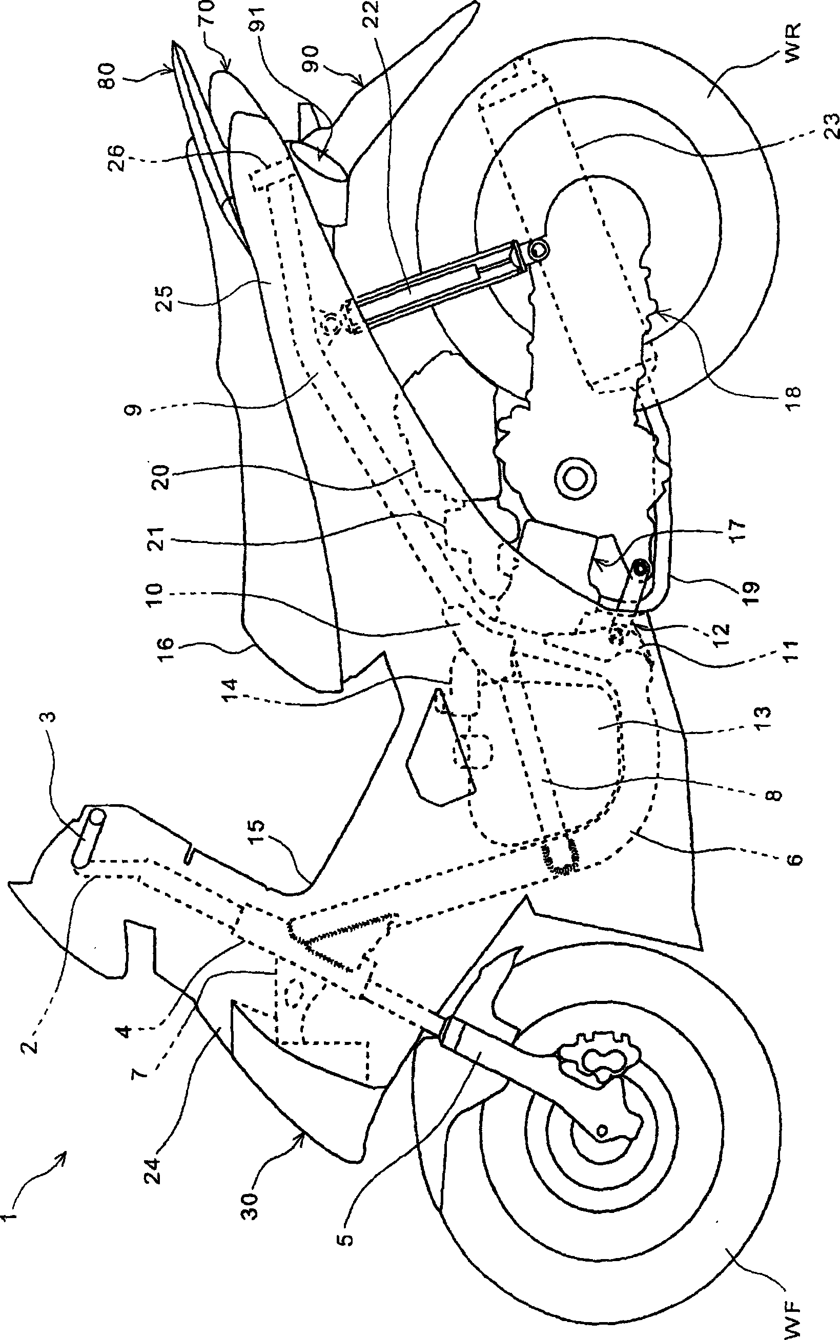
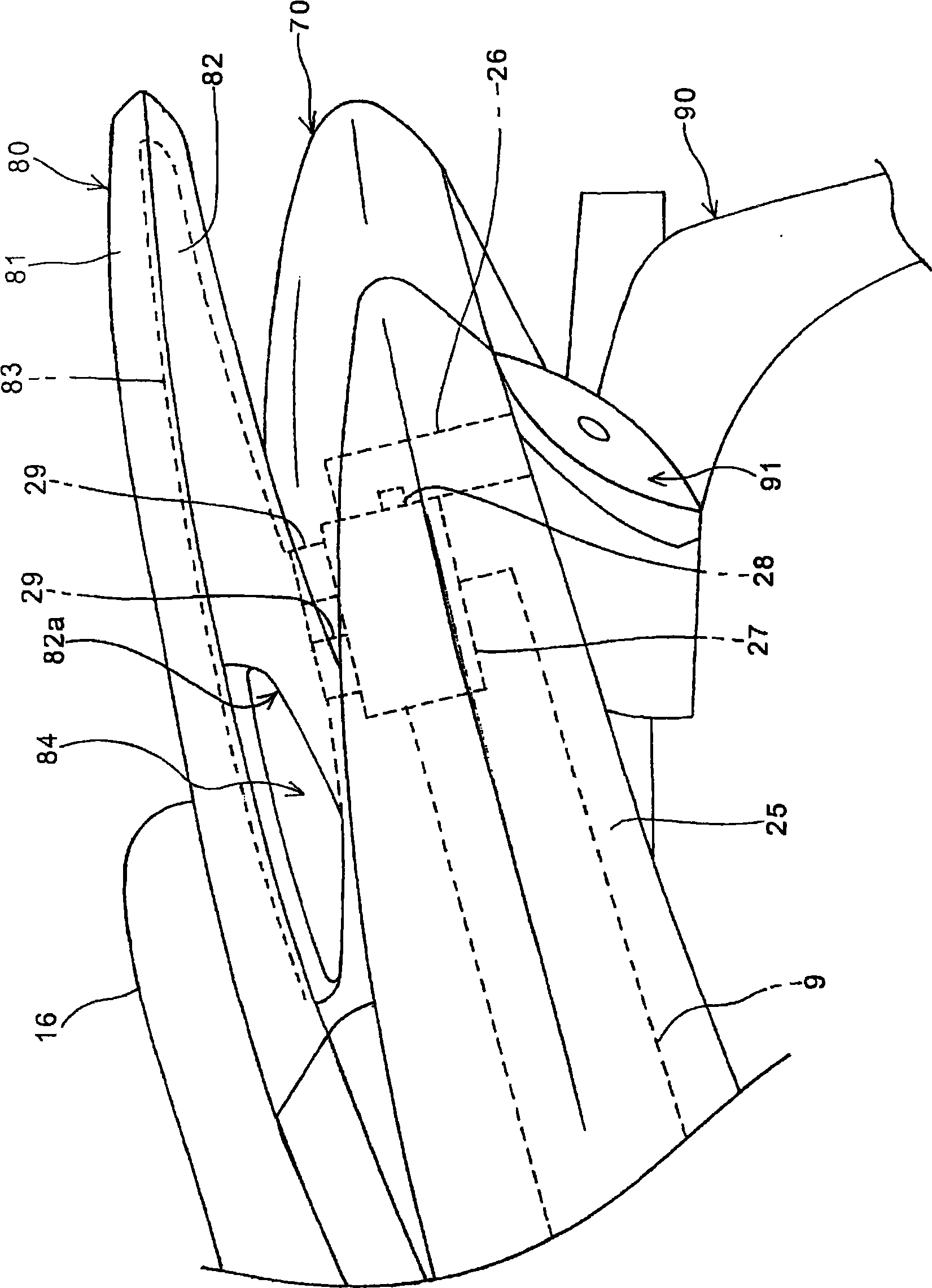
[0052] Hereinafter, preferred embodiments of the present invention will be described in detail with reference to the accompanying drawings. figure 1 It is a side view of the motorcycle 1 which concerns on one Embodiment of this invention. The two-wheeled vehicle 1 is a small saddle-type vehicle including a unit swing type power unit incorporating a continuously variable transmission. A cylindrical head pipe 4 is fixed in front of the vehicle body of a pair of left and right main frames 6 , and a front wheel WF is rotatably supported at the lower ends of a pair of left and right front forks 5 pivotally fixed to the head pipe 4 . .

[0053] The front wheels WF are steered by a steering handle 2 connected to a shaft (not shown) rotatably supported on a head pipe 4 , and a pair of left and right grips 3 are provided on the steering handle 2 . In addition, the head pipe 4 is covered from the front-rear direction of the vehicle body by the front cover 24 and the cover panel 15 as ...


PUM


Abstract

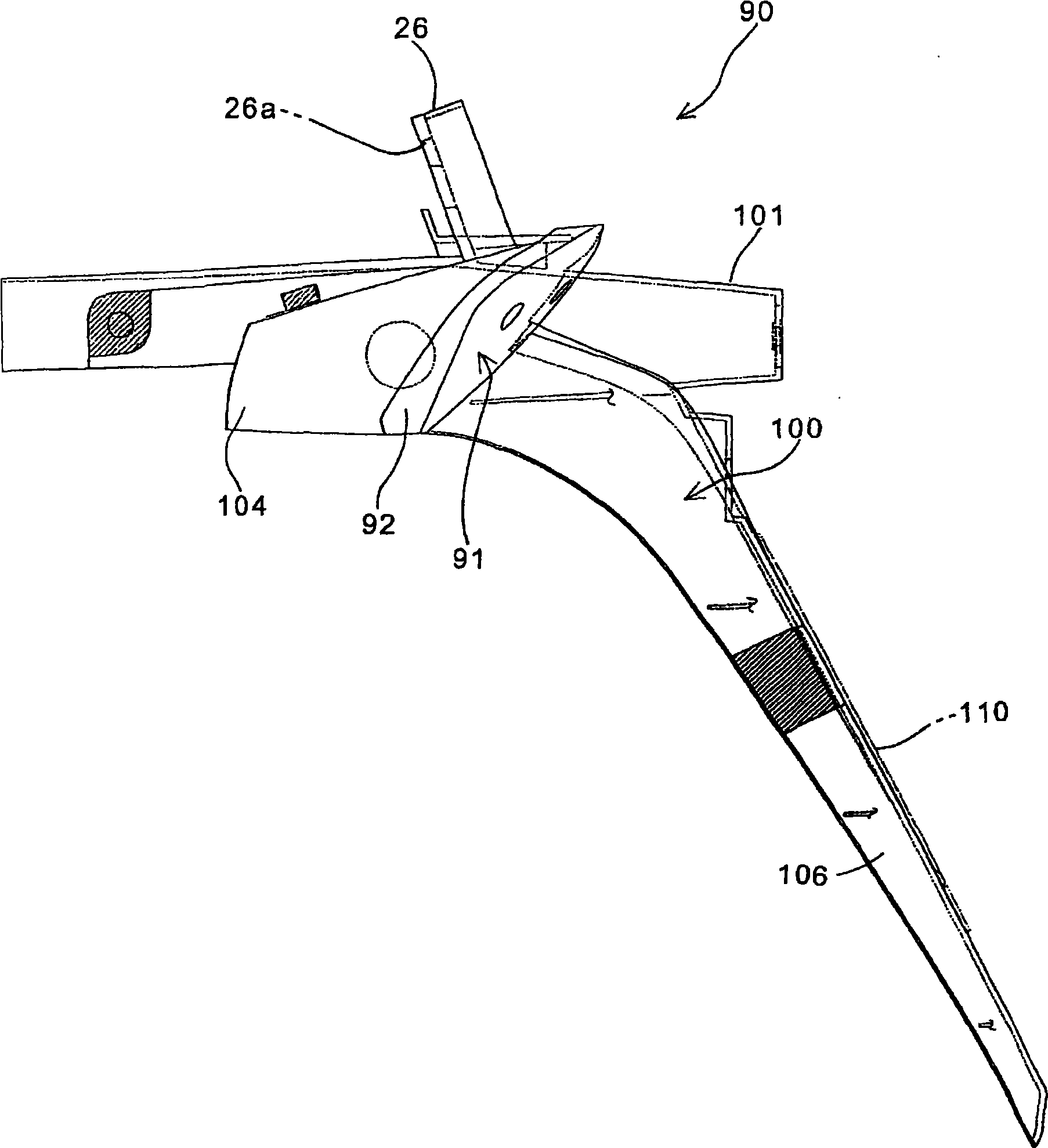
The invention provides a rear illuminating apparatus of vehicles, which enables the whole bulb to be held in an integral cover part of a rear splash guard. The rear illuminating apparatus (90) has a base body part (100) utilizing the cover part (104) of a rear turn light (91) and the rear splash guard part (106) of a rear wheel WR. A recess (105) holding a turn light bulb (93) and a lamp holder (95) is formed at the cover part (104), the opening part of the recess (105) is covered by a turn light lens (92), thereby forming the holding space of the illuminating apparatus. The lamp holder (95) of the turn light bulb (93) is supported on a turn light reflector (94) of the recess (105). The turn light reflector (94) is fixed on the cover body (104) by bolts (99) in opposite direction relativeto the direction of covering the lens part. A through hole (97) communicated with the space inside the vehicle is installed on the lateral wall of the recess (105), and the wiring (96) of the turn light (93) is guided to the space inside the vehicle through the through hole (97).

Description

technical field [0001] The present invention relates to a vehicle rear lighting device, and more particularly to a vehicle rear lighting device in which the entire bulb is housed in a rear fender-integrated cover. Background technique [0002] Conventionally, a rear lighting device for a vehicle is known in which a cover of the lighting device is integrally formed with a rear fender (fender of a rear wheel). [0003] Patent Document 1 discloses a rear lighting device for a vehicle in which a cover of a lighting device and a rear fender are integrally formed with a resin component. A pair of left and right turn signals, and the rear fender is arranged behind and above the rear wheels. [0004] Patent Document 1: Japanese Patent Application Publication No. 3-126732 [0005] However, in the structure disclosed in Patent Document 1, since the brake bulb and the steering bulb are supported at the bottom of the recess formed in the cover, the sockets on the back side of the two ...

Claims


Application Information

Patent Timeline
Patent Type & Authority Applications(China)
IPC IPC(8): B60Q1/30
CPCB60Q1/44B62J6/04B62J11/19
Inventor 中岛广幸滝本幸子立石康
Owner HONDA MOTOR CO LTD
Learn More