Time-of-arrival location method for emission source

A technology for time-difference positioning and emission source, which is used in positioning, measuring devices, instruments, etc., can solve the problems of cumbersome positioning of acoustic emission sources and troublesome calculation formulas.

Inactive Publication Date: 2009-08-12
SHENYANG INSTITUTE OF CHEMICAL TECHNOLOGY
View PDF0 Cites 15 Cited by
  • Summary
  • Abstract
  • Description
  • Claims
  • Application Information

AI Technical Summary

Problems solved by technology

In practice, in order to obtain the calculation equation of the location of the acoustic emission source and simplify the calculation, the location of the receiver of the acoustic emission signal (hereinafter referred to as the sensor) is usually arranged according to a specific regular geometric figure. According to the geometric figure of the sensor arrangement, the time difference positioning The method can be divided into square positioning method, equilateral triangle positioning method and spherical triangle positioning method, etc., but the calculation formula for determining the position of the acoustic emission source derived from the above-mentioned various methods is still relatively cumbersome, which makes the positioning of the acoustic emission source more cumbersome.

Method used


Image

  • Time-of-arrival location method for emission source
  • Time-of-arrival location method for emission source
  • Time-of-arrival location method for emission source

Examples


Embodiment

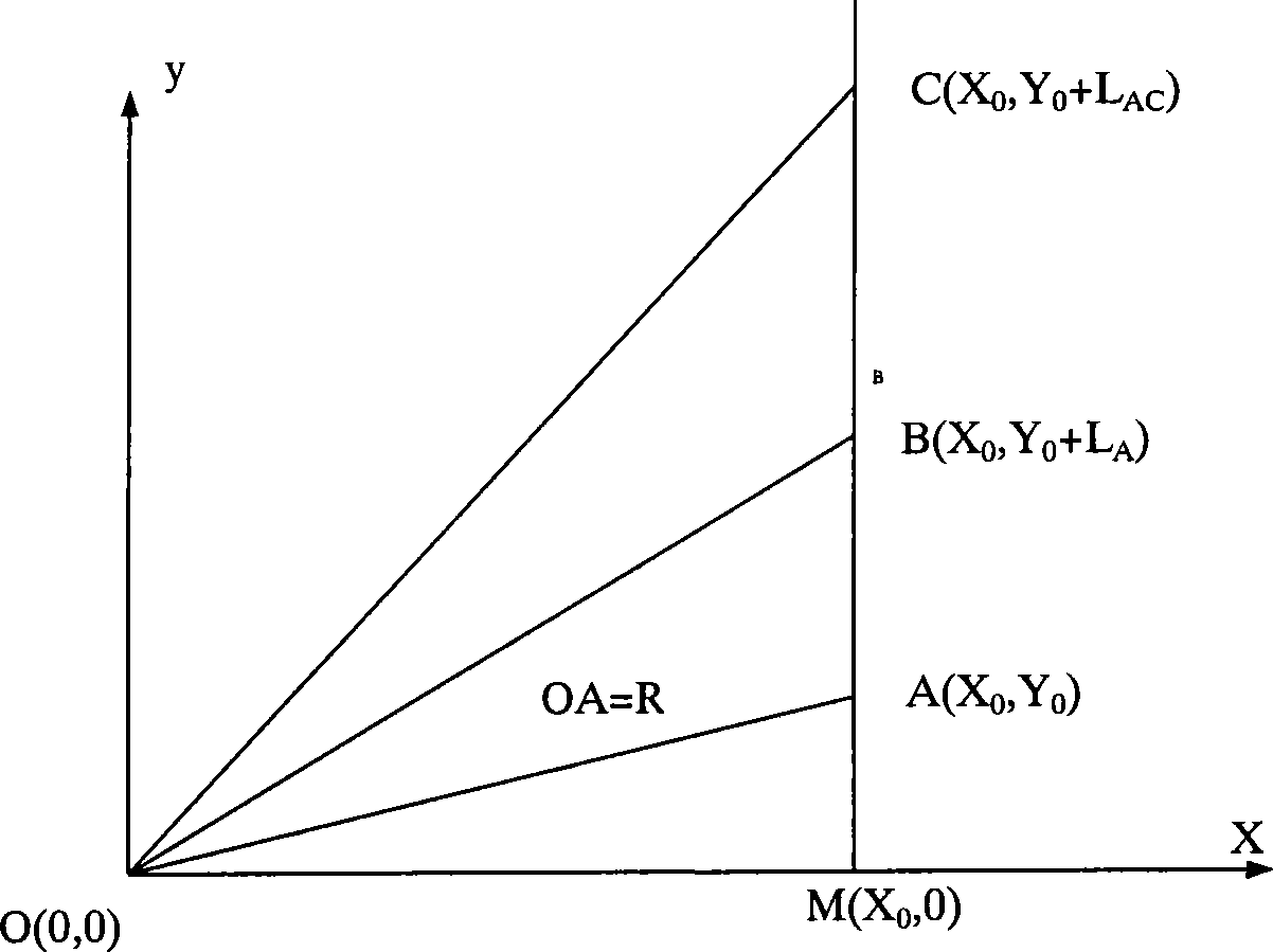
[0018] Example: see figure 1 As shown, in the plane Cartesian coordinate system xoy, the origin of the coordinates is the source of the acoustic emission, the y-axis is parallel to the straight line AC, and the three sensors are arranged in a straight line, respectively placed at A(X 0 , Y 0 ), B(X 0 , Y 0 +L AB ), C(X 0 , Y 0 +L AC ), let OA=R, OB=R+R AB , OC=R+R AC . T AB and T AC . If the propagation velocity of the sound wave is V (which can be measured in advance with a simulated acoustic emission source), then R AB =VT AB , R AC =VT AC , can be regarded as a known quantity.

[0019] M(X 0 , 0) is the intersection of the x-axis and the straight line AC, and the triangles MOA, MOB, and MOC are all right-angled triangles. According to the Pythagorean theorem:

[0020] R 2 = X 0 ...


PUM


Abstract

The invention relates to a method for positioning an acoustic emission source, which mainly comprises the following steps: arranging at least three signal receivers according to a linear relation; receiving a signal sent by the acoustic emission source; determining time differences between the arrivals of the signal at the signal receivers; and determining the position of the acoustic emission source according to the distance between the signal receivers and time differences between the arrivals of the signal at the signal receivers. The method has the advantages that the acoustic emission source positioning operation is simplified due to a simple geometric figure in which signal sensors are arranged and a simple computing formula for determining the position of the acoustic emission source. The method also can be conveniently applied to other like positioning problems. The position of the acoustic emission source is determined finally by the time differences between the arrivals of the signal at the different receivers and the transmission speed of the signal.

Description

technical field [0001] The invention relates to a method for locating an emission source, in particular to a method for locating a source of sudden acoustic emission. Background technique [0002] Determining the location of the acoustic emission source is one of the main goals of acoustic emission testing, and it is also an important indicator for evaluating acoustic emission instruments. How to improve the positioning accuracy of the acoustic emission source and simplify the positioning work of the acoustic emission source to the greatest extent is an important index for the detection and evaluation of the acoustic emission and the performance evaluation of the acoustic emission monitoring instrument. Therefore, it is of great significance to improve the sound source localization method. [0003] Acoustic emission source location method can be divided into time difference location method, area location method, correlation location method and pattern recognition location m...

Claims


Application Information

Patent Timeline
Patent Type & Authority Applications(China)
IPC IPC(8): G01S5/18
Inventor 张忠宁田健金志浩
Owner SHENYANG INSTITUTE OF CHEMICAL TECHNOLOGY
Why Eureka
Try Eureka