Printing head mounting device and 3D printing equipment

An installation device and 3D printing technology, applied in the field of additive manufacturing, can solve the problems of cumbersome disassembly and assembly, and high requirements for stroke processing of ball plunger modules, and achieve the effect of reducing operation difficulty, simplifying positioning and distance, and improving installation efficiency

Pending Publication Date: 2021-12-17
NINGXIA KOCEL MOLD
View PDF0 Cites 0 Cited by
  • Summary
  • Abstract
  • Description
  • Claims
  • Application Information

AI Technical Summary

Problems solved by technology

However, the stroke and processing requirements of the ball plunger module

Method used


Image

  • Printing head mounting device and 3D printing equipment
  • Printing head mounting device and 3D printing equipment
  • Printing head mounting device and 3D printing equipment

Examples


Embodiment approach 1

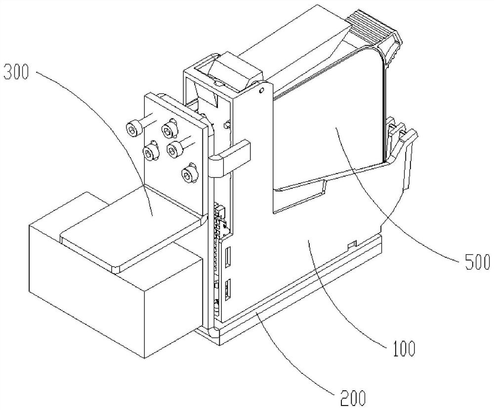
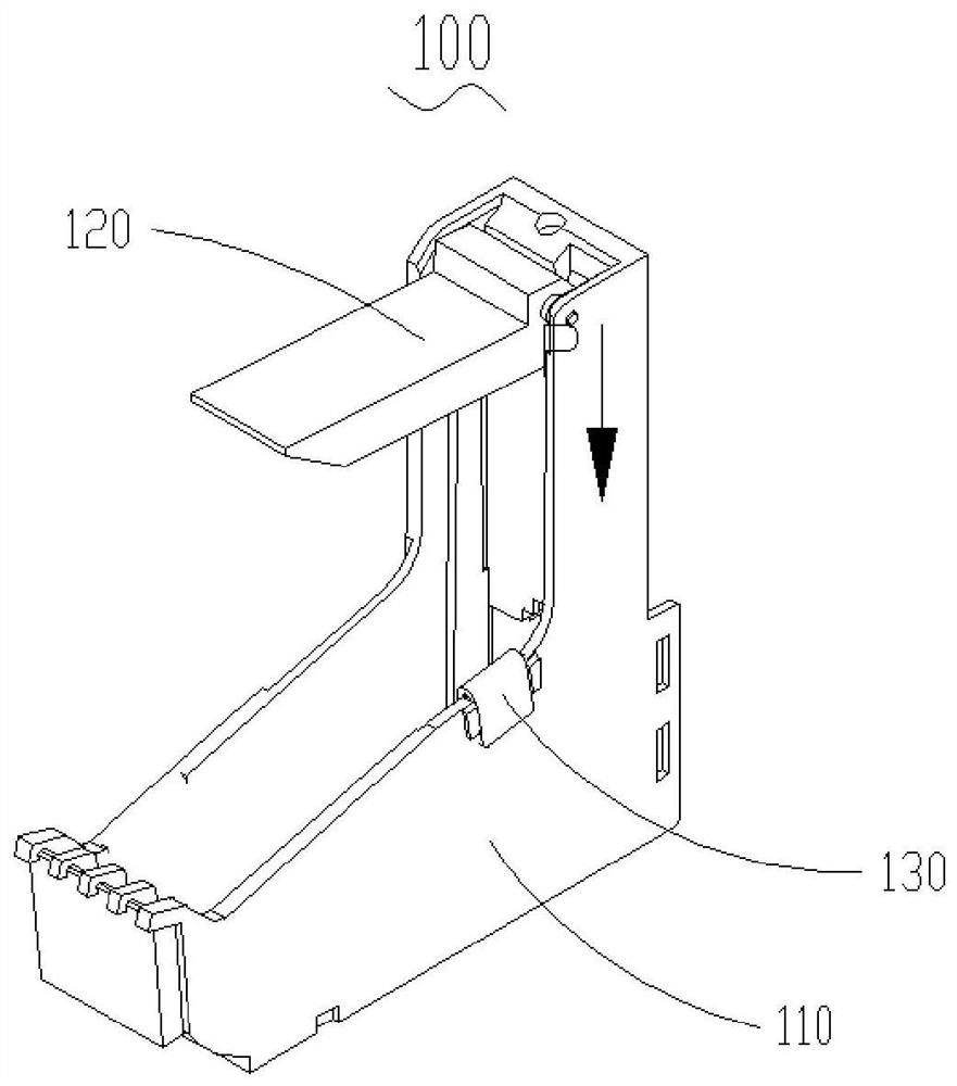
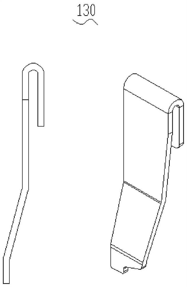
[0028] Such as Figure 1 to Figure 4 As shown, it is an installation device of a print head 500, the installation device includes a frame base assembly 100, a connection assembly 200 and an adjustment assembly 300; the frame base assembly 100 is seated on the connection assembly 200, And the two are fixed by bolts; one end of the adjustment assembly 300 is connected with the connection assembly 200 through bolts, and the other end of the adjustment assembly 300 is connected with the driving mechanism in the print head 500 assembly. The frame-type base assembly 100 includes a frame-type fixing base 110, the frame-type fixing base 110 is a cuboid structure with a certain open surface, and the inner space of the cuboid structure is the accommodating space of the print head 500, which is used to hold Support and position printing head 500, and be provided with window at the bottom of described frame type fixed seat 110, described window is used for printing head 500 ejection outle...

Embodiment 2

[0033] like Figure 5 to Figure 7 As shown, it is a schematic diagram of the structure of the board-type base assembly in use. The board-type base assembly 400 includes a board-type fixing seat 410 and a board-type pressing plate 420. The plate-type base assembly 400 of the head 500 space. The plate-shaped fixing seat 410 is provided with a first positioning structure 411 and a second positioning structure 412 for supporting and positioning the print head 500. The first positioning structure 411 is used to support the print head 500, so that the printing There is a certain distance between the head 500 and the powder-spreading surface to support the print head 500, that is, the print head 500 is located on the first positioning structure 411; the second positioning structure 412 is a stepped structure, with The printing head 500 can be stably placed in the plate-shaped fixing seat 410 to form a fastening force and a supporting force in a direction opposite to the first positi...


PUM


Abstract

The invention discloses a printing head mounting device, and belongs to the technical field of additive manufacturing. The printing head mounting device is used for solving the problem that a printing head in additive manufacturing equipment is complex to mount and debug. The printing head mounting device comprises a base assembly, a connecting assembly (200) and an adjusting assembly (300), the base assembly is arranged on the connecting assembly (200), one end of the connecting assembly (200) is connected with one end of the adjusting assembly (300), and the other end of the adjusting assembly (300) is connected with a driving mechanism; and the base assembly is provided with a cavity capable of containing a printing head (500). The printing head for the 3D printing equipment is simpler and more convenient to mount, routine adjustment in maintenance and operation is more convenient and simpler, and the manufacturing cost and the operation and maintenance cost of the equipment are greatly reduced.

Description

technical field [0001] The invention relates to the technical field of additive manufacturing, in particular to a device for additive manufacturing. Background technique [0002] The motion system of current additive manufacturing equipment adopts the form of modules or linear motors. During the operation of the equipment, powder is easy to enter the module and / or linear motor, which will cause damage to the module and / or linear motor. In order to prevent powder from entering the module and / or linear motor during the operation of the equipment, set The corresponding protection makes the installation and maintenance of the equipment more complicated; at the same time, it also makes the equipment larger. In addition, the installation and fixation of the print head is to fill the gap with thin copper sheets and steel sheets of different thicknesses between the stopper and the print head to achieve the function of fixing the print head; each time you install, you need to try di...

Claims


Application Information

Patent Timeline
IPC IPC(8): B29C64/209B29C64/20B29C64/245B33Y30/00
CPCB29C64/209B29C64/20B29C64/245B33Y30/00
Inventor 麦恒嘉刘轶蒙南华杜银学王军伟马睿任建玺杨保宁
Owner NINGXIA KOCEL MOLD
Why Eureka
Try Eureka