
Debugging control implementing method and system

An implementation method and breakpoint technology, which is applied in the computer field, can solve problems such as low efficiency, many debugging control processes, and missing breakpoints, so as to meet high real-time requirements, have obvious advantages in debugging efficiency, and avoid missing breakpoints. Effect

Active Publication Date: 2009-08-12
ZTE CORP
View PDF0 Cites 17 Cited by
  • Summary
  • Abstract
  • Description
  • Claims
  • Application Information

AI Technical Summary

Problems solved by technology

For example, in the above example, when the five threads are equal, the effective breakpoint events only account for one-fifth of the breakpoint events. If other threads (A1, B1, D1, E1) call the common function code (function1) chance More, the frequency of occurrence is faster, more invalid breakpoints occur, and the debugging efficiency will be lower;
[0024] 2. There are many invalid debugging control processes in the debugging process
The main purpose of this kind of control is to avoid missing breakpoint events (if the current breakpoint is also effective for other threads, if other threads are not stopped when processing the breakpoint event, other threads where the breakpoint takes effect may have already run through this breakpoint Point position, thus causing the situation of missing breakpoints), but this processing has brought additional interference to other threads, and also affects the efficiency of debugging
[0025] Taken together, existing debuggers suffer from inefficiencies
Embedded systems have relatively high real-time requirements, and low efficiency may directly lead to logic errors. Therefore, a more efficient and stable debugger solution is needed for embedded systems.

Method used


Image

  • Debugging control implementing method and system
  • Debugging control implementing method and system
  • Debugging control implementing method and system

Examples


Embodiment Construction

[0055] The present invention will be described in further detail below with specific embodiments in conjunction with the accompanying drawings.

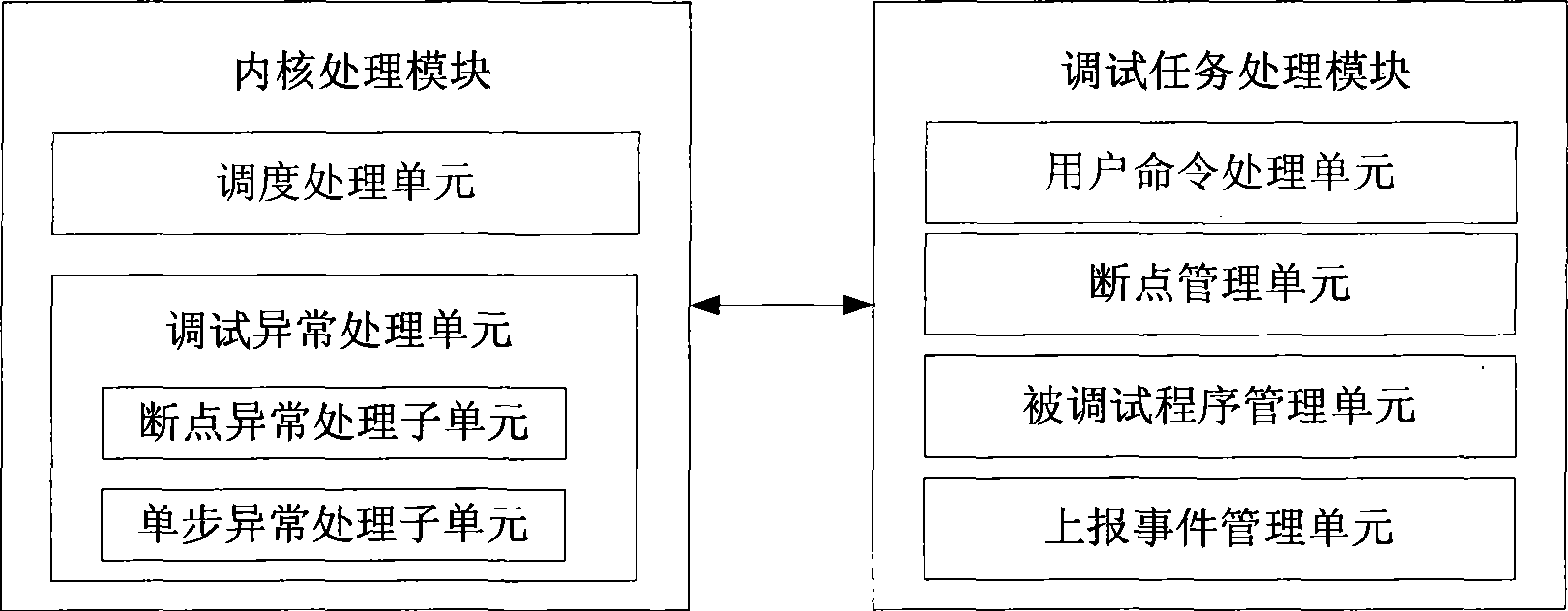
[0056] A specific implementation of the debugging control system of the present invention, such as figure 1 As shown, it includes a debugging task processing module and a kernel processing module. The kernel processing module is the main part of this embodiment, which realizes the control of the debugged program and the processing of debugging logic such as breakpoint and single step; the debugging task processing module mainly completes the user interface part, and cooperates with the kernel processing module to realize the entire debugging control system.

[0057] In this embodiment, the debugging task processing module can be deployed in two ways: one is to completely place the module on the target machine; the other is to use cross-debugging, the module is divided into two parts, one part It is set on the target machine, and the...


PUM


Abstract

The invention discloses a method for realizing debugging control. The method comprises a breakpoint-inserting process and a breakpoint-deleting process, wherein the breakpoint-inserting process is realized by inserting a breakpoint only effective into a current thread or a task cut in when a kernel is scheduled, and the breakpoint-deleting process is realized by deleting the breakpoint when the kernel schedules the thread or the task required to be cut out. The invention also discloses a debugging control system. The method inserts the breakpoint effective into the current thread or the task cut in when the kernel is scheduled and does not insert code segments in breakpoints ineffective into the current thread or the task, thus all debugging events generated in the debugging process are effective events, so that the method avoids the influence of ineffective events on debugging and improves debugging efficiency. As the method inserts the breakpoint when the thread or the task is scheduled and cut in, the method does not need to control the stop and restoration of the other threads or tasks while processing the current debugging event, thereby further improving debugging efficiency and avoiding the occurrence of breakpoint-missing events.

Description

technical field [0001] The invention relates to the debugger technology in the computer field, in particular to a method and system for realizing debug control that can be used for multi-thread or multi-task. Background technique [0002] With the continuous development of information technology, the scale and complexity of software continue to increase, and there are more requirements for debugger functions; at the same time, there are higher requirements for debugging efficiency and debugging stability. [0003] At present, there are already many relatively mature integrated development and debugging environments on the general-purpose desktop operating system. But there is no mature debugger implementation in the embedded system at present. The main reasons are: firstly, the operating systems of many embedded systems do not support debugging and cannot debug user programs; secondly, embedded systems have relatively high requirements for debuggers, because compared with g...

Claims


Application Information

Patent Timeline
Patent Type & Authority Applications(China)
IPC IPC(8): G06F11/36
Inventor 崔云峰程圣宇刘东张毅向红
Owner ZTE CORP
Learn More