Power transmission device

A technology for power transmission devices and transmission components, applied in the direction of transmission devices, belts/chains/gears, couplings, etc., can solve the problems of increased breaking torque, unsuitable for belt protection, engine protection, etc., and achieve a small number of parts , low-cost effect

Active Publication Date: 2009-08-19
三电株式会社
View PDF1 Cites 6 Cited by
  • Summary
  • Abstract
  • Description
  • Claims
  • Application Information

AI Technical Summary

Problems solved by technology

If a fracture-type torque limiter is designed on the basis of considering the fatigue of this material, the instantaneous fracture torque will increase, which is not suitable for the original purpose, that is, it is not suitable for belt protection and engine protection.

Method used


Image

  • Power transmission device
  • Power transmission device
  • Power transmission device

Examples


Embodiment Construction

[0055] Hereinafter, preferred embodiments of the present invention will be described with reference to the drawings.

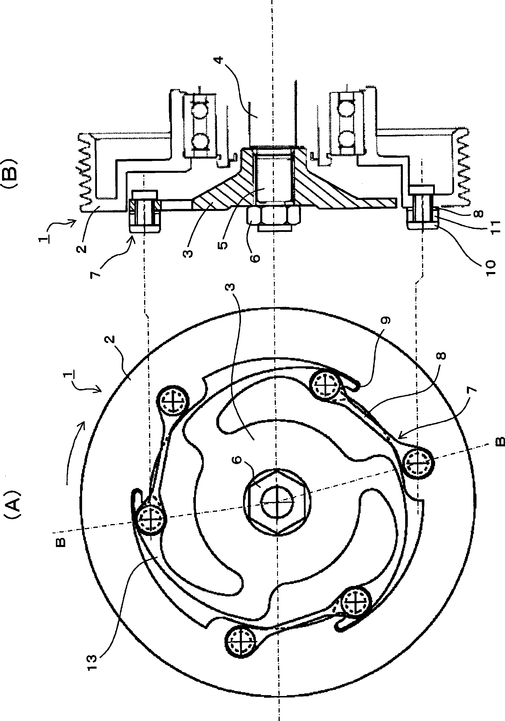
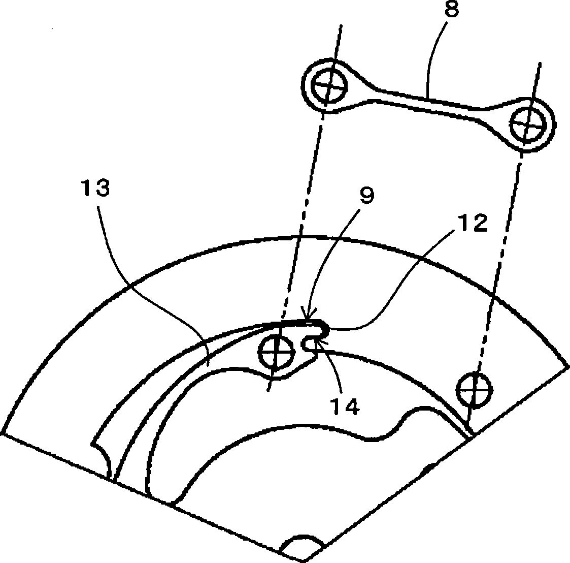
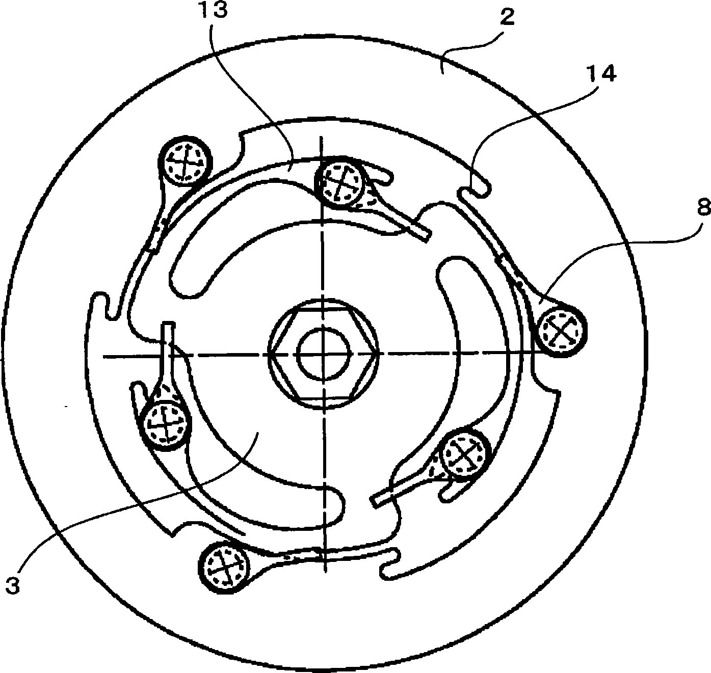
[0056] Figure 1 ~ Figure 4 A power transmission device according to Embodiment 1 of the present invention is shown. exist figure 1 Among them, the symbol 1 represents the whole power transmission device, and the power transmission device 1 includes figure 1 The two parts that rotate in the direction of the arrow in (A), that is, the pulley 2 as the driving body that receives the driving force from the engine; Hub body 3 on the end of the main shaft 4 of the compressor. These pulleys 2 and the hub body 3 are connected by the connecting portion 7, and the torque of the pulley 2 as the driving body is transmitted to the hub body 3 as the driven body, and when the driving load of the driven body exceeds a predetermined value, As will be described later, the transmission of torque is interrupted by fracture of the constituent members of the connection portio...


PUM


Abstract

A power transmission device in which a driven body and a driving body for driving the driven body are rotated in the same direction and are connected to each other by a connection section to transmit torque of the driving body to the driven body and in which the transmission of the torque from the driving body is interrupted when a drive load on the driven body exceeds a predetermined level. The connection section is constructed by combining separate elements that are a positive torque transmission member, and a negative torque transmission mechanism or a negative torque transmission member. The positive torque transmission member transmits torque in the normal rotational direction and interrupts transmission of torque from the driving body by breaking itself when a drive load on the driven body exceeds the predetermined level. The negative torque transmission mechanism or the negative torque transmission member can transmit torque in the reverse rotational direction. In the power transmission device, fatigue of materials of the connection section is suppressed and torque is accurately interrupted at a target interruption torque value.

Description

technical field [0001] The present invention relates to a power transmission device, and relates to a power transmission device suitable for transmitting, for example, driving force from an engine of a vehicle to equipment mounted on the vehicle (for example, a compressor for a vehicle air conditioner). Background technique [0002] The power transmission device often needs to have the function of a torque limiter that cuts off the transmission of excessive driving force. For example, when driving the compressor by transmitting the driving force from the engine of the vehicle to the compressor of the vehicle air conditioner, when the driving load on the side of the compressor as the driven body becomes excessive for some reason, in order to protect the It is preferable to cut off the transmission of the driving force (torque transmission) between the vehicle engine and the belt. [0003] Various mechanisms are known as the torque transmission cut-off mechanism as described ...

Claims


Application Information

Patent Timeline
Patent Type & Authority Applications(China)
IPC IPC(8): F16D9/00F16H35/10
CPCF16D9/04F16D9/00F16D3/60
Inventor 高井和彦
Owner 三电株式会社
Why Eureka
Try Eureka