
Floating chuck apparatus and floating chuck unit

A technology of floating chucks and chucks, which is applied in the direction of chucks, etc., can solve the problems of reduced productivity, difficulty in ensuring positioning accuracy, and tilting of the chuck axis, and achieve the effects of improving productivity, realizing positioning accuracy, and realizing compactness

Inactive Publication Date: 2013-07-17
SEIKO INSTR INC
View PDF2 Cites 0 Cited by
  • Summary
  • Abstract
  • Description
  • Claims
  • Application Information

AI Technical Summary

Problems solved by technology

However, in the case of adopting the method of stacking linear guides as the above-mentioned floating mechanism, since the mechanism itself cannot be avoided in size, the chucks cannot be arranged in parallel, and there is a problem that the productivity is lowered.
In addition, since lubricating oil or the like is used to smooth the movement of the linear guide, there is a possibility that the lubricating oil or the like may contaminate the workpiece.
[0010] In addition, in the case of using a spring, vibration, etc. due to its elasticity may cause the axis of the chuck to tilt, making it difficult to ensure high positioning accuracy.
Also, when using the magnet method, since the workpiece may be magnetized, it is not suitable for processing precision parts

Method used


Image

  • Floating chuck apparatus and floating chuck unit
  • Floating chuck apparatus and floating chuck unit
  • Floating chuck apparatus and floating chuck unit

Examples


Embodiment Construction

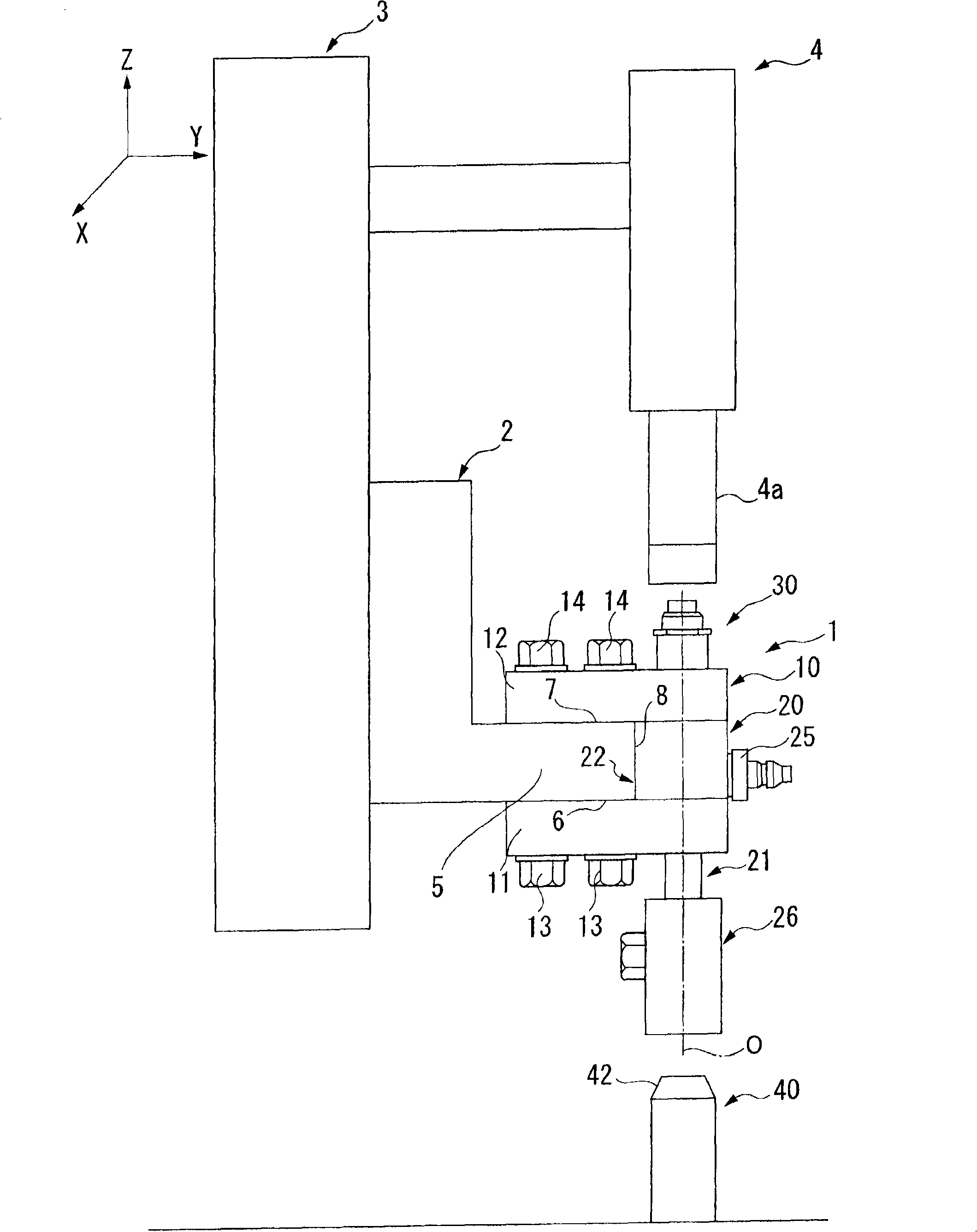
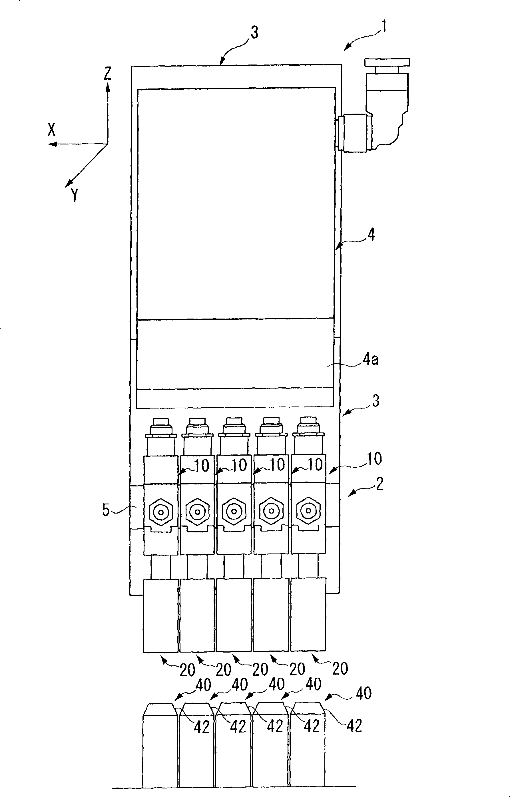
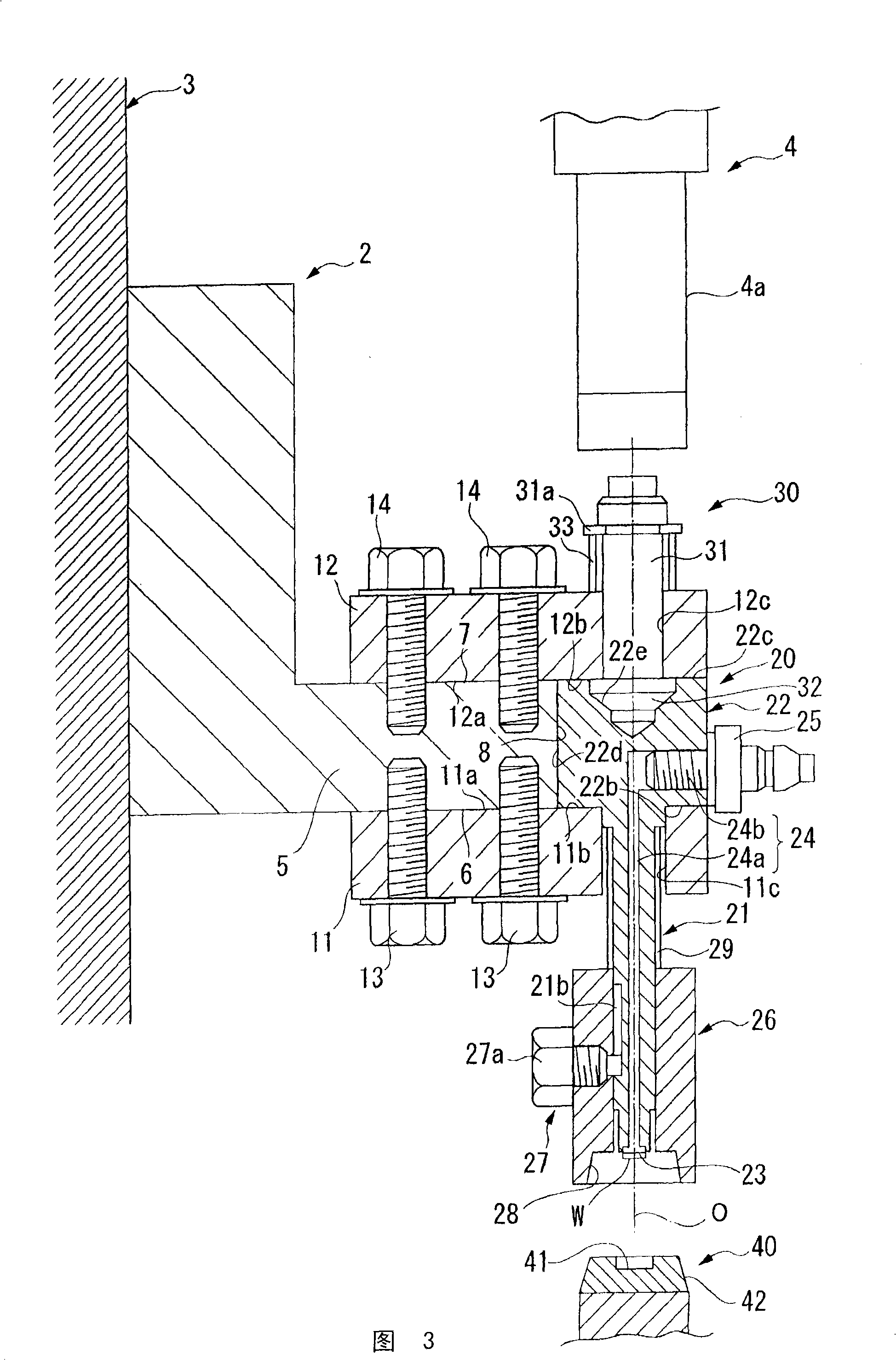
[0051] Hereinafter, embodiments of the present invention will be described with reference to the drawings. Here, an embodiment of the floating chuck device of the present invention will be described together with a floating chuck unit of the present invention incorporating the floating chuck device.

[0052] figure 1 It is a side view showing the floating chuck unit of this embodiment, figure 2 It is a side sectional view showing the floating chuck unit of this embodiment, and FIG. 3 is a side sectional view of a floating chuck device constituting the floating chuck unit, Figure 4 It is a partially enlarged view of Fig. 3 .

[0053] Such as figure 1 and figure 2 As shown, the floating chuck unit 1 of this embodiment is constituted by arranging a plurality of (five in this embodiment) floating chuck devices 10 in parallel, and each of the floating chuck devices 10 is installed by means of an angle iron (angle) 2 on the mobile substrate 3 . Furthermore, directly above t...


PUM


Abstract

The invention provides a floating chuck apparatus and a floating chuck unit with compaction implemented by simple composition. The floating chuck apparatus(10) has a shaft(2) extending in an up-and-down direction so that the absorption part at the front end of the shaft can absorb workpieces for retaining the chuck(20) of the workpiece(W) which can be floating relatively to the movable substrate(3); the floating chuck unit has a plurality of parallel-arranged floating chuck apparatus; in the floating chuck apparatus or the floating chuck unit, the chuck(20) has a flange part(22) and a chuck through hole(11c) with an plug-in shaft(21), and a first guide block(11) for supporting the flange part(22) and a second guide block(12), cooperated with the first guide block, for clamping the flange part(22) from upside; gaps(n1,n2) are formed between the first guide block(11) and the flange part(22), and between the chuck through hole(11c) and the shaft(21).

Description

technical field [0001] The present invention relates to a floating chuck device that supports a relative movement mechanism for a chuck that holds a workpiece by suction so as to be able to float, and a floating chuck unit configured by arranging a plurality of the floating chuck devices in parallel. Background technique [0002] For example, in order to assemble minute components in the manufacture of precision equipment, etc., small chucks that hold these minute components are required. As such a chuck, conventionally, as disclosed in Patent Document 1, for example, there is known a structure in which a workpiece (microcomponent) is sucked by vacuum. In this chuck, a porous suction part is arranged at the front end of the chuck, and the workpiece is sucked to the side of the suction part by bringing the workpiece into contact with the front end surface of the suction part and sucking air based on vacuum from the base end surface side of the suction part. front face. [0...

Claims


Application Information

Patent Timeline
Patent Type & Authority Patents(China)
IPC IPC(8): B23B31/02
Inventor 高比良彰小林大介山田笃志
Owner SEIKO INSTR INC
Learn More