
Floating spindle

A main shaft and moving ring technology, applied in the field of floating main shaft, can solve the problems of low processing efficiency, broken tool castings, rising product defect rate, etc., and achieve the effect of prolonging the service life and avoiding rigid collision.

Inactive Publication Date: 2018-07-06
四川威能特科技有限公司
View PDF8 Cites 0 Cited by
  • Summary
  • Abstract
  • Description
  • Claims
  • Application Information

AI Technical Summary

Problems solved by technology

[0002] At present, most domestic factories use manual or hand-held pneumatic or electric tools for grinding, grinding, and filing in the process of removing burrs and flashes from metal parts, which will easily lead to an increase in the defective rate of products, and the processing efficiency is very low. After processing, there will be problems such as rough and uneven surface of the product. There are also electric or pneumatic tools installed by robots for automatic grinding. However, due to the rigidity of the mechanical arm and the inaccurate positioning, it is easy to break the knife or casting during the removal of irregular burrs. damaged condition

Method used

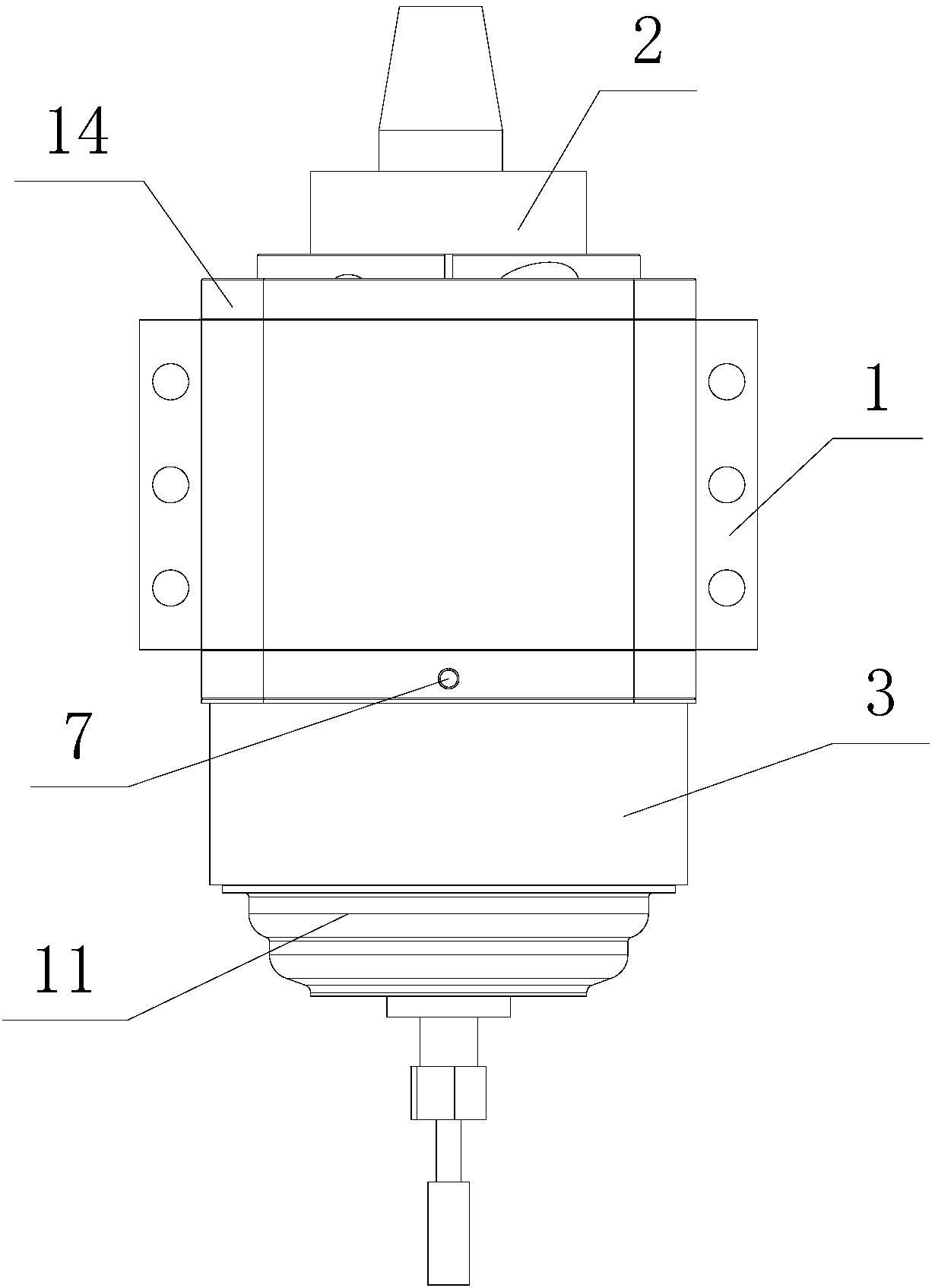
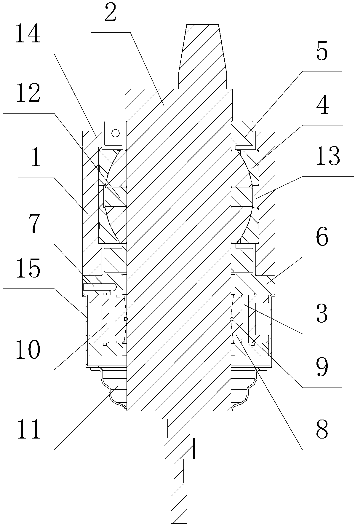

Image

  • Floating spindle
  • Floating spindle

Examples


Embodiment 1

[0020] Such as figure 1 and figure 2 As shown, the floating spindle provided by this embodiment includes a coaxial installation housing 1, a spindle body 2 and an air pressure chamber 3. Inside the housing 1, the lower part is located in the air pressure chamber 3, the top of the installation housing 1 is provided with an end cover 14, and the installation housing 1 is provided with an angular contact joint bearing 4, and the angular contact joint bearing 4 is sleeved on the upper part of the main shaft body 2. An inner lining ring 12 is provided between the inner wall of the angular contact spherical plain bearing 4 and the outer wall of the main shaft body 2, and an outer lining ring 13 is provided between the outer wall of the angular contact spherical plain bearing 4 and the inner wall of the installation shell 1. The top of the angular contact spherical plain bearing 4 and the The bottom is respectively provided with a spindle limit lock ring 5, and the two spindle limi...

Embodiment 2

[0023] This embodiment is basically the same as Embodiment 1, except that the air inlet 7 is changed, and an air pressure regulating device is connected to the outside of the air inlet 7 through an air pipe, and the air pressure regulating device includes an air storage tank and an air pressure regulating valve. , the air inlet 7 is connected to the air storage tank through an air delivery pipe, and the air delivery pipe is provided with an air pressure regulating valve.

[0024] Working principle of the present invention: add compressed air into the air pressure chamber 3 from the air inlet 7 (the air pressure in the air pressure chamber 3 can be adjusted between 0.1-0.8Mpa), when the air pressure chamber 3 is filled with pressure gas, according to the principle of gas pressure, the air pressure The floating moving ring 8 in the chamber 3 will automatically move to the center of the air pressure chamber 3, the main shaft body 2 is set on the floating moving ring 8, the main sh...


PUM


Abstract

The invention discloses a floating spindle. The floating spindle comprises a mounting shell, a spindle body and an air pressure chamber which are coaxially arranged, wherein the spindle is arranged inthe mounting shell and the air pressure chamber; an angular contact joint bearing is arranged in the mounting shell; the angular contact joint bearing is arranged on the spindle body in a sleeving manner; spindle limiting clamp rings are separately arranged at the top and bottom of the angular contact joint bearing; the mounting shell is connected to the air pressure chamber through a mounting plate; an air inlet communicating to the air pressure chamber is formed in one side of the mounting plate; a floating movable ring is arranged in the air pressure chamber; the floating movable ring is arranged on the lower part of the spindle body in a sleeving manner; a shock absorbing rubber ring is also arranged between the inner wall of the floating movable ring and the outer wall of the spindlebody; a cylinder cover is arranged on the outer side of the air pressure chamber in a sleeving manner; a dustproof cover is also arranged in the bottom of the air pressure chamber; and the dustproofcover is arranged in the bottom of the spindle body in a sleeving manner. The floating spindle disclosed by the invention can improve the processing efficiency and the processing quality effectively,and can avoid damage of parts and tools in processing.

Description

technical field [0001] The invention belongs to the technical field of machining spindles, and in particular relates to a floating spindle. Background technique [0002] At present, most domestic factories use manual or hand-held pneumatic or electric tools for grinding, grinding, and filing in the process of removing burrs and flashes from metal parts, which will easily lead to an increase in the defective rate of products, and the processing efficiency is very low. After processing, there will be problems such as rough and uneven surface of the product. There are also electric or pneumatic tools installed by robots for automatic grinding. However, due to the rigidity of the mechanical arm and the inaccurate positioning, it is easy to break the knife or casting during the removal of irregular burrs. damaged condition. Contents of the invention [0003] The technical problem to be solved by the present invention is to provide a floating spindle with a simple structure and...

Claims


Application Information

Patent Timeline
Patent Type & Authority Applications(China)
IPC IPC(8): B24B41/04
CPCB24B41/04
Inventor 胡勇
Owner 四川威能特科技有限公司
Learn More