
A bump welding fixture for the middle and lower glass guide rail and bracket of the front door of an automobile

A glass guide rail and bump spot welding technology, applied in welding equipment, manufacturing tools, welding equipment, etc., can solve the problems of virtual welding, spot welding and small welding area, and achieve the effect of ensuring quality, improving production efficiency, and eliminating gaps

Active Publication Date: 2019-02-01
宁波金通金属科技有限公司
View PDF5 Cites 0 Cited by
  • Summary
  • Abstract
  • Description
  • Claims
  • Application Information

AI Technical Summary

Problems solved by technology

[0002] The middle and lower glass guide rail of the front door in the car needs to be welded with the matching bracket at the end when assembling. Due to the need for assembly, spot welding is required between the front door middle and lower glass guide rail and the bracket, but the welding area of ​​the spot welding is relatively small. Yes, but when welding the middle and lower glass guide rails of the front door and the bracket, there will be a gap no matter how they are placed. This gap also exists during welding, which will easily lead to virtual welding during spot welding. Virtual welding is relatively Serious defects, it will be scrapped if there is a false welding, so there is an urgent need for a special fixture that can solve the above problems to improve product quality and production efficiency

Method used


Image

  • A bump welding fixture for the middle and lower glass guide rail and bracket of the front door of an automobile
  • A bump welding fixture for the middle and lower glass guide rail and bracket of the front door of an automobile
  • A bump welding fixture for the middle and lower glass guide rail and bracket of the front door of an automobile

Examples


Embodiment Construction

[0020] Below in conjunction with specific embodiment, further illustrate the present invention. It should be understood that these examples are only used to illustrate the present invention and are not intended to limit the scope of the present invention. In addition, it should be understood that after reading the teachings of the present invention, those skilled in the art can make various changes or modifications to the present invention, and these equivalent forms also fall within the scope defined by the appended claims of the present application.

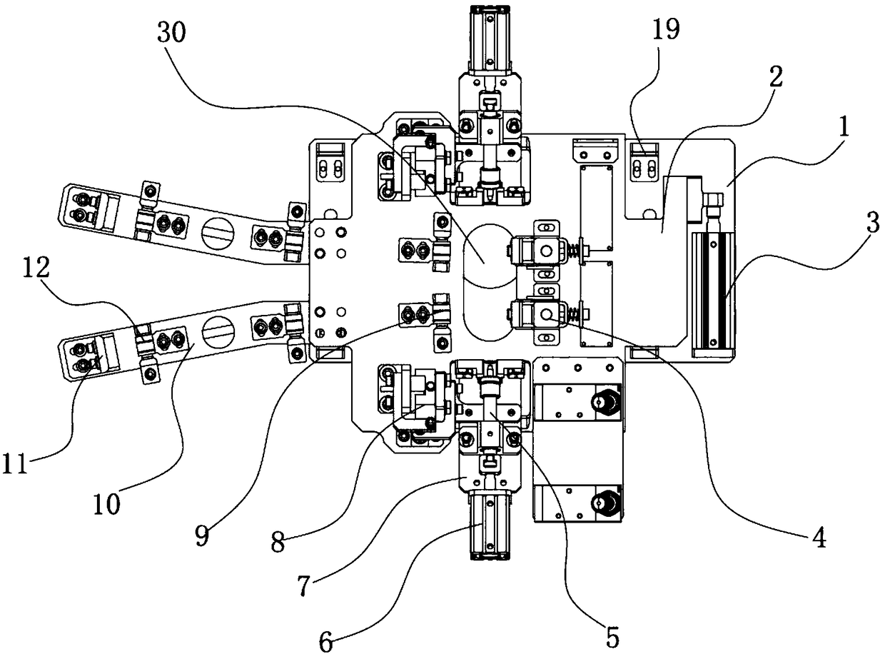
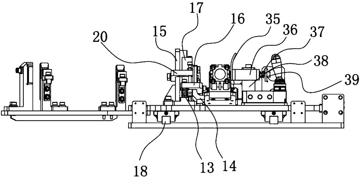
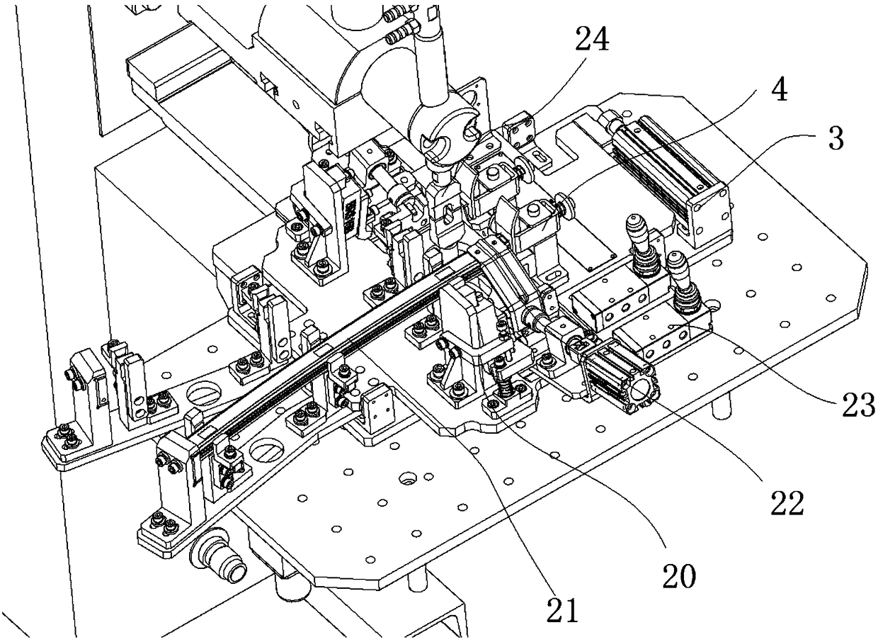
[0021] Such as Figure 1-5 As shown, the embodiment of the present invention relates to a bump welding fixture for the middle and lower glass guide rails and brackets of the front door of an automobile, including a table panel 1 and a moving plate 2, and is characterized in that a pair of Front and rear guide rails 18, on which the moving plate 2 is slidably installed, and the middle part of the moving plate 2 has a strip-shap...


PUM


Abstract

The invention relates to a projection spot welding jig for a front door middle-lower glass guide rail and a support of an automobile. The projection spot welding jig comprises a table board and a moving plate and is characterized in that a pair of guide rails in the front-back direction are arranged above the table board and are provided with the moving plate in a sliding mode, a long strip-shaped through hole is formed in the middle of the moving plate, a pair of elastic end locating assemblies are installed at one side of the long strip-shaped through hole side by side, end supports are installed at the other side of the long strip-shaped through hole side by side, and a pair of extending locating plates corresponding to the end supports are installed at the end, close to the end supports, of the moving plate side by side; and a pair of support-clamping floating assemblies are symmetrically arranged above the part, close to the two ends of the long strip-shaped through hole, of the moving plate, and one sides of the support-clamping floating assemblies are connected to floating guiding and limiting assemblies. According to the projection spot welding jig, the structure is ingenious, the floating assemblies are adopted for clamping the supports, the supports can float in the spot welding process, a gap between the support and the front door middle-lower glass guide rail can be eliminated, pseudo soldering is prevented, and the welding quality is guaranteed.

Description

technical field [0001] The invention relates to the field of auto parts processing equipment, in particular to a bump welding jig for the middle and lower glass guide rails and brackets of the front door of an automobile. Background technique [0002] The middle and lower glass guide rail of the front door in the car needs to be welded with the matching bracket at the end when assembling. Due to the need for assembly, spot welding is required between the front door middle and lower glass guide rail and the bracket, but the welding area of ​​the spot welding is relatively small. Yes, but when welding the middle and lower glass guide rails of the front door and the bracket, there will be a gap no matter how they are placed. This gap also exists during welding, which will easily lead to virtual welding during spot welding. Virtual welding is relatively For serious defects, it will be scrapped if there is a false welding, so there is an urgent need for a special fixture that can...

Claims


Application Information

Patent Timeline
Patent Type & Authority Patents(China)
IPC IPC(8): B23K11/36B23K37/04B23K11/11B23K11/14
CPCB23K11/115B23K11/14B23K11/36B23K37/0435
Inventor 贺铭璐李郑叶胜药刘剑波谈春梅
Owner 宁波金通金属科技有限公司
Learn More