Parallel mechanism with three freedom degrees of twice rotation and once motion
What is AI technical title?
AI technical title is built by Patsnap AI team. It summarizes the technical point description of the patent document.
A degree of freedom and parallel technology, applied in the direction of manipulators, manufacturing tools, etc., can solve problems such as difficult calibration and complex kinematic models, and achieve the effect of simple kinematic model, simple and reliable structure, and high rigidity
Inactive Publication Date: 2010-10-13
ZHEJIANG SCI-TECH UNIV
View PDF9 Cites 0 Cited by
Summary
Abstract
Description
Claims
Application Information
AI Technical Summary
This helps you quickly interpret patents by identifying the three key elements:
Problems solved by technology
Method used
Benefits of technology
Problems solved by technology
[0004] The two-transfer-one-shift three-degree-of-freedom parallel mechanisms disclosed in existing publications (such as US6431802, WO0025976, ZL200610013608.3, EP1123175, CA2349579, DE59905578D, ES2198991T, ZL200710057179.4) all have complex kinematic models, resulting in real-time Difficult to control and calibrate
Method used
Image
Click on the blue label to locate the original text in one second.
Reading with bidirectional positioning of images and text.
Examples
Embodiment 1
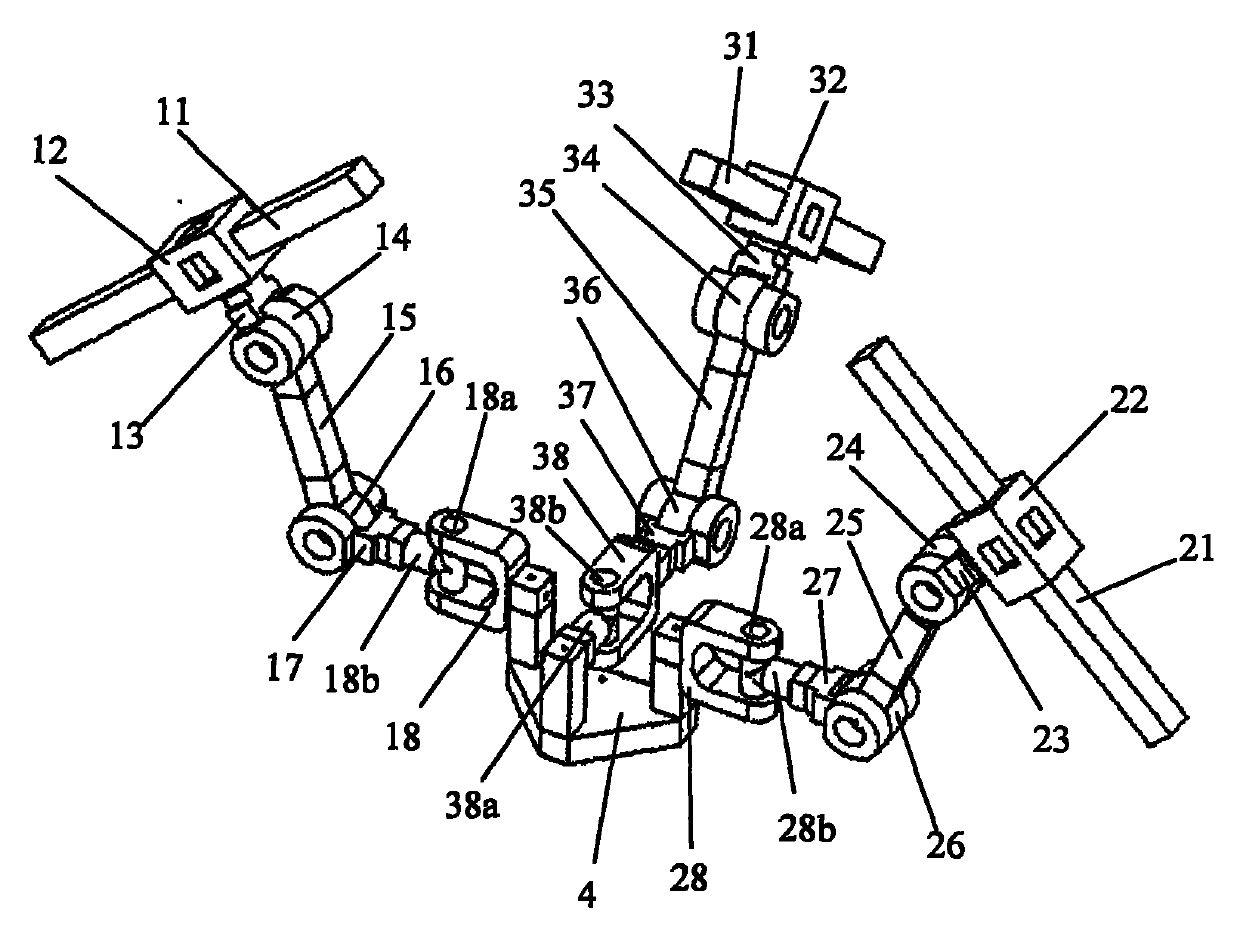
[0037] Such as figure 1 As shown, the moving platform 4 is connected with the frame 11, 21 and 31 through three branches with the same structure, and the moving pairs 12, 22, 32 in the branch are not parallel to each other and are connected with the frame 11, 21 and 31 respectively, and the connecting rod 13, One end of 23,33 is connected with moving pair 12,22,32 respectively, and the other end of connecting rod 13,23,33 is connected with rotating pair 14,24,34 respectively, and the axis of rotating pair 14,24,34 is respectively connected with moving The axes of pair 12, 22, 32 are vertical, one end of connecting rod 15, 25, 35 is respectively connected with rotating pair 14, 24, 34, and the other end of connecting rod 15, 25, 35 is connected with rotating pair 16, 26, 36 respectively , one end of the connecting rod 17, 27, 37 is connected with the revolving pair 16, 26, 36 respectively, and the other end of the connecting rod 17, 27, 37 is respectively connected with the sec...
Embodiment 2
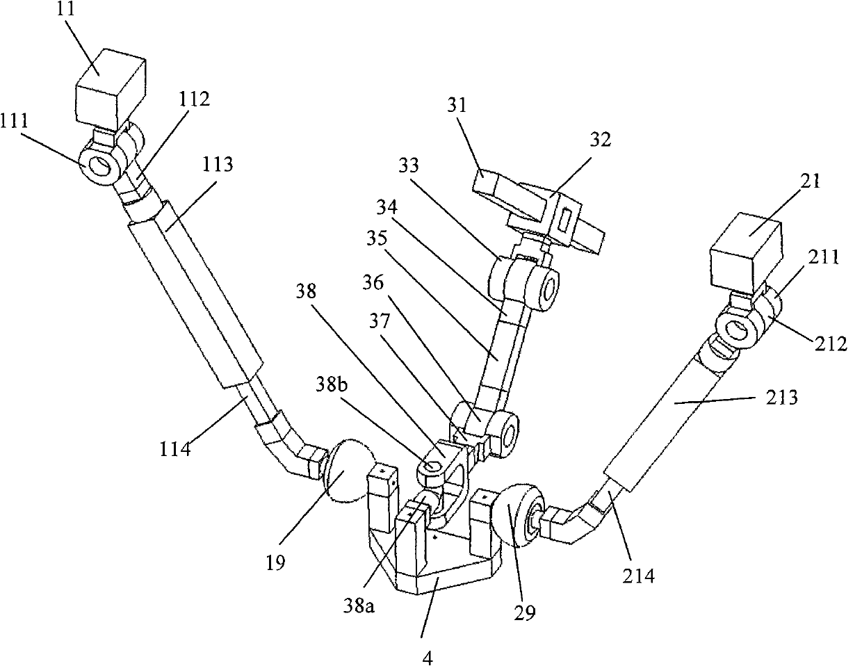
[0039] Such as figure 2 As shown, the moving platform 4 is connected to the frame 11, 21 and 31 through three branches with the same structure, the revolving pairs 111, 211, 311 are connected to the frame 11, 21 and 31 respectively, and one end of the connecting rod 112, 212, 312 is respectively It is connected with the rotating pair 111, 211, 311, the other ends of the connecting rods 112, 212, 312 are respectively connected with the moving pairs 113, 213, 313, and one end of the connecting rods 114, 214, 314 is respectively connected with the moving pairs 113, 213, 313, The other end of connecting rod 114,214,314 is connected with rotating pair 16,26,36 respectively, and one end of connecting rod 17,27,37 is connected with rotating pair 16,26,36 respectively, and the other end of connecting rod 17,27,37 One end is respectively connected with the second rotating shaft 18b, 28b, 38b of the universal joint 18, 28, 38, and the moving platform 4 is respectively connected with th...
Embodiment 3
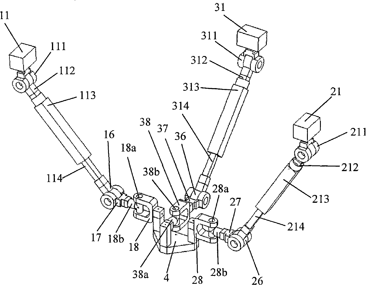
[0041] Such as image 3 As shown, the moving platform 4 is connected to the frame 11, 21 and 31 through three branches with the same structure, the revolving pairs 111, 211, 311 are connected to the frame 11, 21 and 31 respectively, and one end of the connecting rod 112, 212, 312 is respectively It is connected with the rotary pair 111, 211, 311, the other ends of the connecting rods 112, 212, 312 are respectively connected with the rotary pairs 116, 216, 316, and one end of the connecting rods 15, 25, 35 is respectively connected with the rotary pairs 116, 216, 316, The other end of connecting rod 15,25,35 is connected with rotating pair 16,26,36 respectively, and one end of connecting rod 17,27,37 is connected with rotating pair 16,26,36 respectively, and the other end of connecting rod 17,27,37 One end is respectively connected with the second rotating shaft 18b, 28b, 38b of the universal joint 18, 28, 38, and the moving platform 4 is respectively connected with the first r...
PUM
Abstract
The invention relates to a parallel mechanism with three freedom degrees of twice rotation and once motion in a robot mechanism. The invention aims at providing the parallel mechanism which has the adThe invention relates to a parallel mechanism with three freedom degrees of twice rotation and once motion in a robot mechanism. The invention aims at providing the parallel mechanism which has the adl lines of first rotating shafts of the two universal hinges in the first branch and the second branch are parallel with each other; central points of the three universal hinges in the three brancaxial lines of first rotating shafts of the two universal hinges in the first branch and the second branch are parallel with each other; central points of the three universal hinges in the three branches are collinear; and the axial line of the first rotating shaft of the universal hinge in the third branch is vertical or parallel to the axial lines of the first rotating shafts of the two universahes are collinear; and the axial line of the first rotating shaft of the universal hinge in the third branch is vertical or parallel to the axial lines of the first rotating shafts of the two universal hinges in the first branch and the second branch.l hinges in the first branch and the second branch.vantages of simple kinematic model, easy control, simple structure, high rapidity and low manufacturing cost. The parallel mechanism with three freedom degrees of twice rotation and once motion is chavantages of simple kinematic model, easy control, simple structure, high rapidity and low manufacturing cost. The parallel mechanism with three freedom degrees of twice rotation and once motion is characterized by comprising a mobile platform, a stand, a first branch, a second branch and a third branch, wherein the first branch, the second branch and the third branch are connected in parallel betwracterized by comprising a mobile platform, a stand, a first branch, a second branch and a third branch, wherein the first branch, the second branch and the third branch are connected in parallel between the mobile platform and the stand; in the three branches, each branch is connected with a first single-freedom-degree motion pair, a second single-freedom-degree motion pair and a universal hingeeen the mobile platform and the stand; in the three branches, each branch is connected with a first single-freedom-degree motion pair, a second single-freedom-degree motion pair and a universal hingein sequence from the stand to the mobile platform, wherein the third branch is additionally provided with a rotating pair between the second single-freedom-degree motion pair and the universal hinge;in sequence from the stand to the mobile platform, wherein the third branch is additionally provided with a rotating pair between the second single-freedom-degree motion pair and the universal hinge;axia
Description
technical field [0001] The invention relates to a robot mechanism, in particular to a parallel mechanism with two rotations, one movement and three degrees of freedom. Background technique: [0002] Parallel robots with few degrees of freedom and less than 6 degrees of freedom are currently the focus of international parallel robotics academia and industry. In practical applications, there are a considerable number of operating tasks that require less than 6 degrees of freedom. At this time, the application of a suitable parallel robot with fewer degrees of freedom can effectively save the cost of system design, manufacturing, control and maintenance. [0003] The 3-DOF parallel mechanism with two rotation degrees of freedom and one movement degree of freedom (referred to as 2 rotations and 1 movement) is a very important class of parallel robots with few degrees of freedom. The 3-PRS / RPS type parallel mechanism is a typical representative of the two-rotation-one-shift thre...
Claims
Application Information
Patent Timeline
Application Date:The date an application was filed.
Publication Date:The date a patent or application was officially published.
First Publication Date:The earliest publication date of a patent with the same application number.
Issue Date:Publication date of the patent grant document.
PCT Entry Date:The Entry date of PCT National Phase.
Estimated Expiry Date:The statutory expiry date of a patent right according to the Patent Law, and it is the longest term of protection that the patent right can achieve without the termination of the patent right due to other reasons(Term extension factor has been taken into account ).
Invalid Date:Actual expiry date is based on effective date or publication date of legal transaction data of invalid patent.

