Three- DOF (degree of freedom) parallel mechanism with two vertical intersecting rotating shafts

A technology of vertical intersection and degrees of freedom, applied in manipulators, manufacturing tools, program-controlled manipulators, etc., can solve the problems of complex structural design, complex mechanism, difficult calibration and control, etc., to improve the rigidity of the mechanism and the bearing capacity, kinematic model Simple, easy-to-control calibration effects

Active Publication Date: 2013-12-11
ZHEJIANG SCI-TECH UNIV
View PDF6 Cites 0 Cited by
  • Summary
  • Abstract
  • Description
  • Claims
  • Application Information

AI Technical Summary

Problems solved by technology

However, this type of mechanism has the following problems: (1) The complex structure design makes it difficult to solve the kinematics; (2) The complex mechanism leads to a small working space; (3) The strong coupling of the motion platform makes trajectory planning and precision control difficult; (4) It is difficult to manufacture high-precision ball pairs
In the existing parallel mechanism, the axis of the two rotational degrees of freedom of the 3-PRS parallel mechanism (referred to as the rotating shaft) changes with the pose of the moving platform, which makes calibration and control very difficult; while the 2-SPR / UPR parallel mechanism although It has two vertical intersecting shafts, but its structure contains a spherical joint, which has big problems in manufacturing accuracy, rotation range and design assembly

Method used


Image

  • Three- DOF (degree of freedom) parallel mechanism with two vertical intersecting rotating shafts
  • Three- DOF (degree of freedom) parallel mechanism with two vertical intersecting rotating shafts
  • Three- DOF (degree of freedom) parallel mechanism with two vertical intersecting rotating shafts

Examples


Embodiment 1

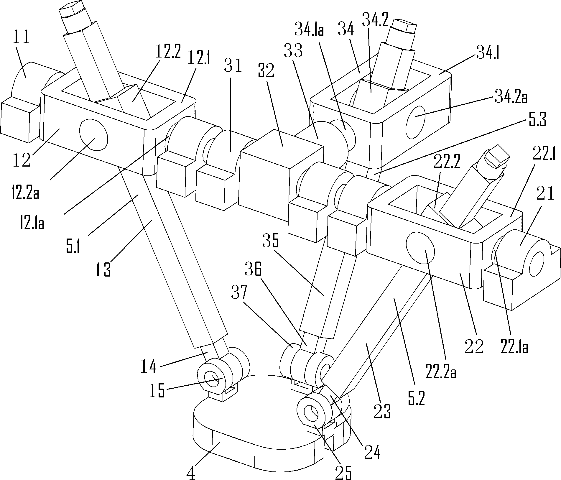
[0038] figure 1As shown, the moving platform 4 is connected in parallel with the frame 11, the frame 21, and the frame 31 through three branches; wherein, in the first branch 5.1, the frame sequentially passes through the universal hinge 12 (the universal hinge includes The outer rotating element 12.1 rotating around the outer rotating shaft 12.1a on the frame and the inner rotating element 12.2 installed on the outer rotating element rotating around the inner rotating shaft 12.2a), the moving pair 13, the connecting rod 14, the rotating pair 15 and the moving The platform 4 is connected; in the second branch 5.2, the frame passes through the universal hinge 22 in turn (the universal hinge includes an external rotating element 22.1 mounted on the frame and rotating around an external rotating shaft 22.1a and a The internal rotating element 22.2 rotating around the internal rotating shaft 22.2a), the moving pair 23, the connecting rod 24, and the rotating pair 25 are connected ...

Embodiment 2

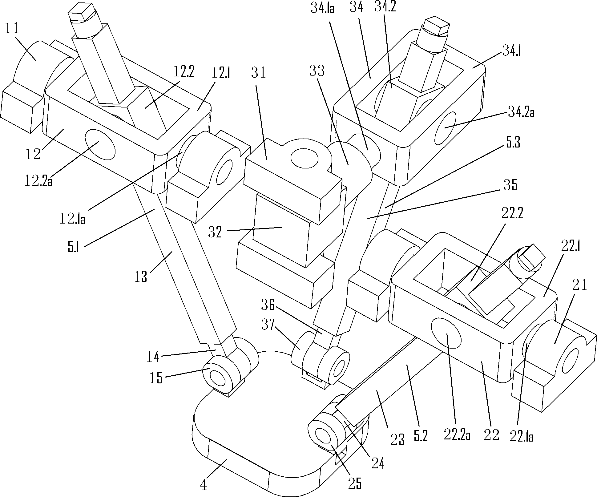
[0044] This example figure 2 As shown, the structure is basically the same as in Embodiment 1; the difference is only:

[0045] In Embodiment 1: the axis of the first rotating pair 32 in the third branch is collinear with the axis of the outer rotating shaft 12.1a of the universal hinge 12 in the first branch and the axis of the outer rotating shaft 22.1a of the universal hinge 22 in the second branch and, in the third branch, the axis of the first rotating pair 32 is perpendicular to the axis of the outer rotating shaft 34.1a of the universal hinge 34; the axis of the inner rotating shaft 34.2a of the universal hinge 34 is parallel to the axis of the second rotating pair 37 and is perpendicular to to the external axis of rotation 34.1a of the hinge 34;

[0046] In Embodiment 2: the axis of the first rotating pair 32 in the third branch is perpendicular to the axis of the outer rotating shaft 12.1a of the universal hinge 12 in the first branch, and the outer rotating shaft 2...

Embodiment 3

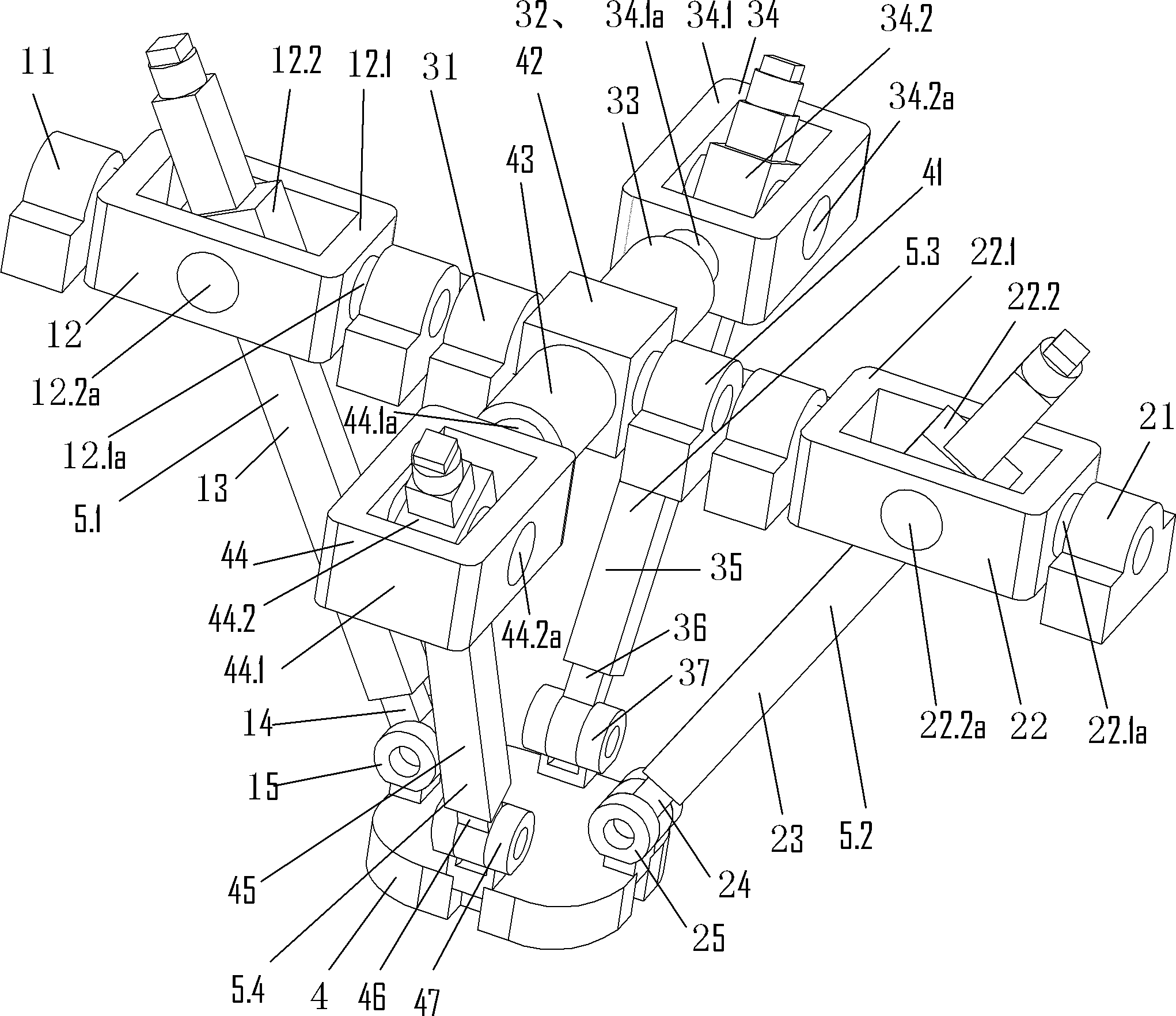
[0048] image 3 As shown, the moving platform 4 is connected in parallel with the frame 11, the frame 21, the frame 31, and the frame 41 through four branches; in the first branch 5.1, the frame passes through the universal hinge 12 successively (the universal hinge includes installation An external rotating element 12.1 rotating around an external rotating shaft 12.1a on the frame and an internal rotating element 12.2 mounted on the external rotating element rotating around an internal rotating shaft 12.2a), a moving pair 13, a connecting rod 14, and a rotating pair 15 Connected with the moving platform 4; in the second branch 5.2, the frame passes through the universal hinge 22 in turn (the universal hinge includes an external rotating element 22.1 mounted on the frame and rotating around the external rotating shaft 22.1a and mounted on the external rotating element The internal rotating element 22.2 rotating around the internal rotating shaft 22.2a), the moving pair 23, the...


PUM


Abstract

The invention relates to a parallel numerical control machine tool and an executing mechanism for a robot with a parallel structure. The invention aims at providing the mechanism with two vertical intersecting rotating shafts, and has the advantages of being simple in structure, convenient to manufacture and install, simple in a kinematics model, easy to calibrate and control. The mechanism has the technical scheme that the three-DOF parallel mechanism with the two vertical intersecting rotating shafts comprises a movable platform, a stander and thee independent elastic adjusting branches which are connected between the movable platform and the stander in parallel. The mechanism is characterized in that the axis of an external rotating shaft of a universal hinge in a first branch is collinear with that of an external rotating shaft of a universal hinge in a second branch; and the axis of a first revolute pair in a third branch, the axis of the external rotating shaft of the universal hinge in the first branch, and the axis of the external rotating shaft of the universal hinge in the second branch are collinear with one another, or the axis of the first revolute pair in the third branch is perpendicular to the external rotating shaft of the universal hinge in the first branch and the collinear axis of the external rotating shaft of the universal hinge in the second branch.

Description

technical field [0001] The invention relates to a machine tool and an executing mechanism of an industrial robot, in particular to a three-degree-of-freedom parallel numerically controlled machine tool with two perpendicularly intersecting rotating shafts and a parallel-connected robot executing mechanism. Background technique [0002] Parallel machine tools have advantages that series mechanisms do not have, such as high rigidity, high precision, strong bearing capacity, and small self-weight load. It is known as a revolution in machine tool structure since the 21st century. At present, most of the parallel machine tools developed internationally are based on the traditional 6-DOF Stewart mechanism (such as CN00102901.0, CN03113115.8, CN200410041753.3, CN200310106458.7); this mechanism consists of a fixed platform, a moving platform and the length connecting them It is composed of adjustable connecting rods. The two ends of the connecting rods are spherical joints and unive...

Claims


Application Information

Patent Timeline
Patent Type & Authority Patents(China)
IPC IPC(8): B23Q1/25B25J9/08
Inventor 李秦川余旭锋陈巧红武传宇崔东苏
Owner ZHEJIANG SCI-TECH UNIV
Why Eureka
Try Eureka