Bicycle with linking lever and cam

A bicycle and lever technology, applied in the field of bicycles, can solve the problems of difficult adjustment and repair, high precision requirements, short service life, etc., and achieve the effect of solving the problem of crank pressure angle, good stability and long service life

Inactive Publication Date: 2009-09-02
NANTONG BAOTIAN PACKING MACHINERY
View PDF1 Cites 9 Cited by
  • Summary
  • Abstract
  • Description
  • Claims
  • Application Information

AI Technical Summary

Problems solved by technology

However, its structure is still relatively complex, and requires high precision, easy to wear, difficult to adjust and repair, and has a short service life.

Method used


Image

  • Bicycle with linking lever and cam
  • Bicycle with linking lever and cam
  • Bicycle with linking lever and cam

Examples


no. 1 example

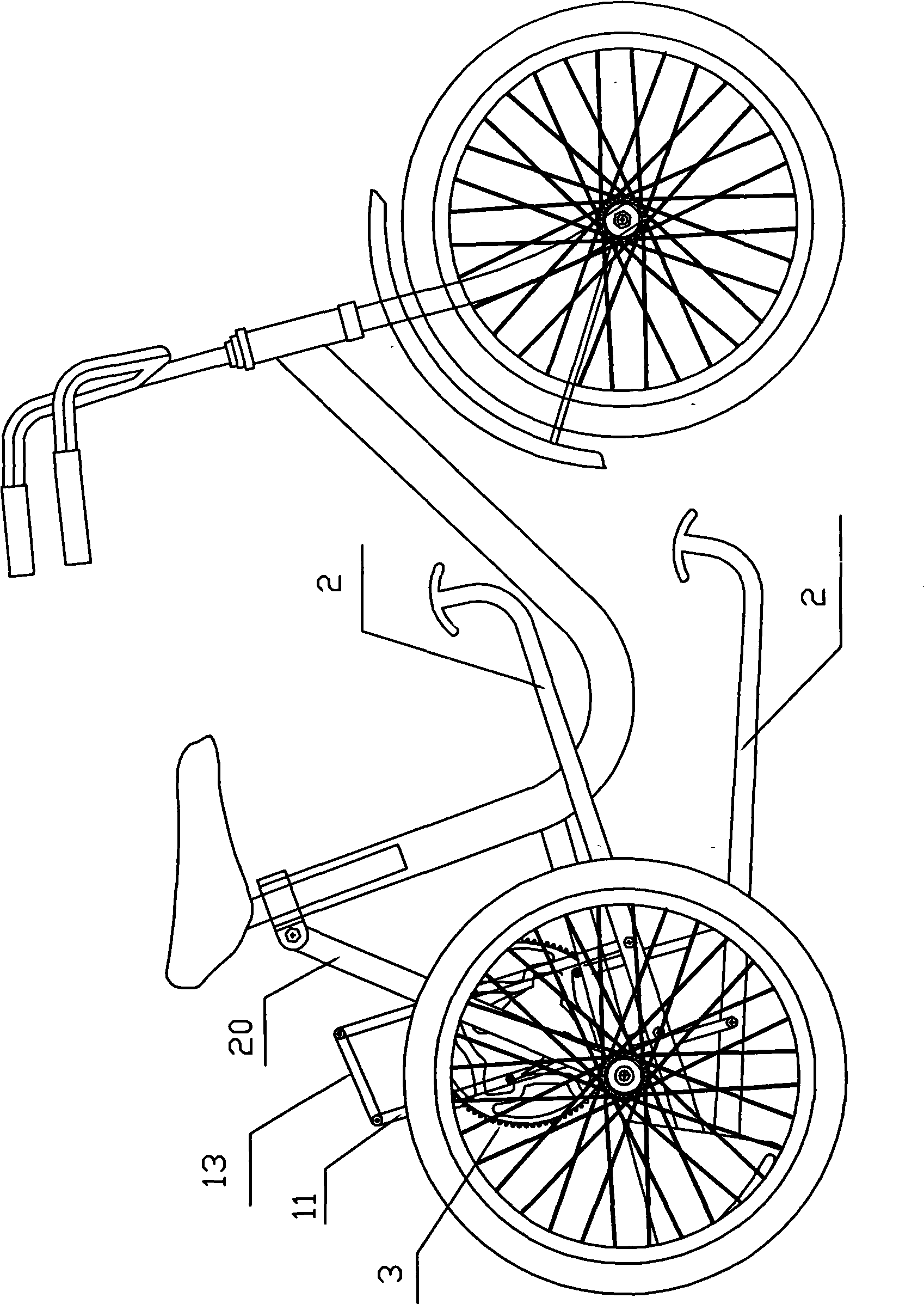
[0035] see figure 1 , figure 2 and image 3 , the invention provides a lever-cam linkage bicycle, which includes a vehicle frame, a front wheel, a rear wheel and a wheel driving device. The wheel driving device includes a lever 2, a swing rod 11, a large gear mechanism 3 and a driven gear 5 arranged on the rear wheel. One end of the lever 2 is a linear drive force application end, and the force application end is connected with a pedal. One end is movably connected to the rear support plate 15 located at the rear end of the vehicle frame, and one end of the fork 11 is hinged to the lever 2. In this embodiment, the lever 2 is provided with two fork 11, each A fork 11 middle position is provided with roller 14, and two fork on the same lever are hinged together by articulated rod 13, and lever 2 forms rolling connection by the roller 14 on the fork 11 and the profile curved surface of driving wheel.

[0036] Such as Figure 4 As shown, the large gear mechanism 3 includes a ...

no. 2 example

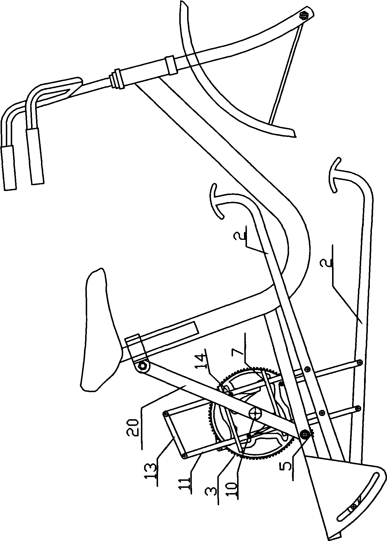
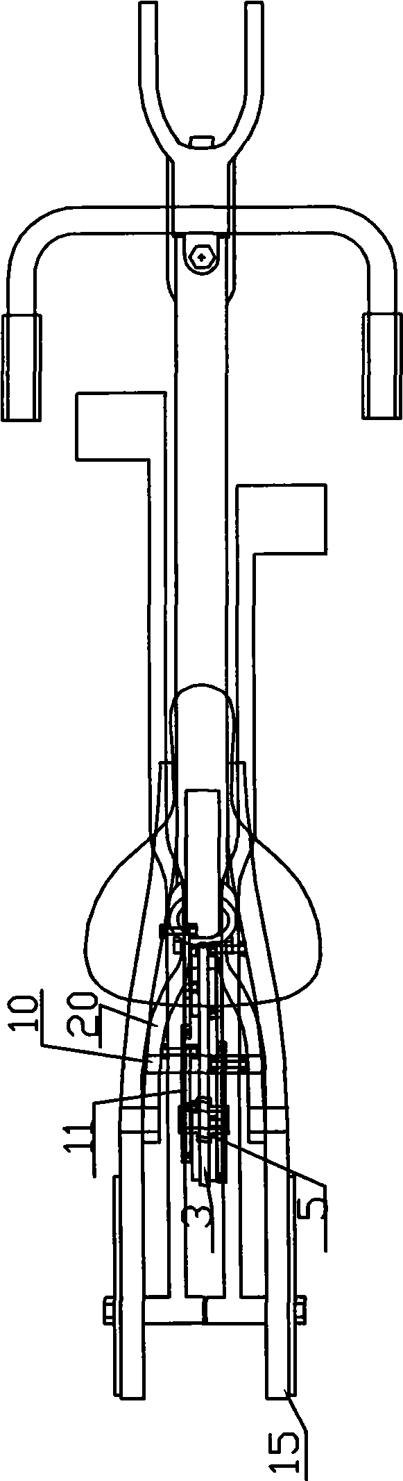
[0044] see Figure 7 to Figure 13 , the present invention also provides a lever-cam linkage bicycle, which includes a vehicle frame 1, a front wheel, a rear wheel and a wheel driving device. The wheel driving device includes a lever 2, a fork 11, a driving wheel, a speed change mechanism 30, and a driven gear 51 arranged on the rear wheel. One end of the lever 2 is a linear drive application end, and the application end is connected with a pedal 16. The other end of the lever is movably connected to the rear support plate 15 located at the rear end of the vehicle frame, and the lower end of the swing link 11 is hinged to the lever 2. In this embodiment, the lever 2 is provided with two swing links 11. Each swing rod 11 is provided with a roller 14 at the upper end position, and the middle and lower ends of the two swing rods 11 on the same lever are hinged together through the hinge rod 13, and the lever 2 is connected with the roller 14 on the swing rod 11. The contoured sur...


PUM


Abstract

The invention discloses a bicycle with linking lever and cam, comprising a vehicle frame, a front vehicle wheel, a back vehicle wheel and a vehicle wheel drive device. The vehicle wheel drive device comprises a lever, swinging rods, a drive wheel and a speed-change mechanism, wherein one end of the lever is a linear drive force-application end, and the other end is movably connected on the vehicle frame; the lower end of each swinging rod is articulated with the lever, a roller is arranged at the upper end of each swinging rod, and the middle lower end of a front swinging rod is movably connected with the middle lower end of a back swinging rod through a hinged bar; the speed-change mechanism comprises a drive gear ring, an intermediate wheel, a driven gear ring, a triangular swinging plate and a pull rod. A contour curved surface which is movably connected with the roller is arranged in the drive wheel, and is provided a farthest lower pull surface, a farthest upper pull surface, a transition surface and a transition surface of delay angle, wherein the farthest lower pull surface and the farthest upper pull surface are symmetrically arranged taking the wheel shaft as the center; and the transition surface is used for communicating the farthest lower pull surface and the farthest upper pull surface. The invention cancels a double foot lost motion part of a crank mechanism to save more labor, thereby the utilization rate of force achieves a favorable state.

Description

technical field [0001] The invention relates to a bicycle, in particular to a lever-cam linkage bicycle. Background technique [0002] Bicycles neither consume energy nor cause environmental pollution, and are widely used by ordinary people as a means of transportation. Especially today, when higher requirements are placed on energy and environmental protection, they are favored by the society. However, so far, the bicycles currently on the market all adopt the driving structure of cranks and sprockets, resulting in many moving parts rotating in a circle, resulting in high failure rate, difficult maintenance, and the defects of frequent oil injection and replacement. [0003] The Chinese patent No. ZL200620141925.9, which has made great improvements to the above defects, discloses a lever-ratchet-linked bicycle, which completely abandons the crank-link mechanism and related components, and replaces the traditional driving method with the up-and-down movement of both feet. T...

Claims


Application Information

Patent Timeline
Patent Type & Authority Applications(China)
IPC IPC(8): B62K3/00B62M1/04B62M11/04B62K3/02B62M1/24
Inventor 胡章地
Owner NANTONG BAOTIAN PACKING MACHINERY
Why Eureka
Try Eureka