Chip discharging device of button hole of button

A discharge device and keyhole technology, which is applied to sewing tools, textiles and papermaking, and clothes piece conveyors, etc., can solve the problems of poor sewing quality and inability to reliably isolate cloth chips, etc.

Inactive Publication Date: 2009-09-02
CHEESIANG SEWING MACHINE S H
View PDF3 Cites 2 Cited by
  • Summary
  • Abstract
  • Description
  • Claims
  • Application Information

AI Technical Summary

Problems solved by technology

In the state where the keyhole hole is produced first and then the edge stroke is performed, the cutting chips remaining in the cloth will be sewn into t

Method used


Image

  • Chip discharging device of button hole of button
  • Chip discharging device of button hole of button
  • Chip discharging device of button hole of button

Examples


Embodiment Construction

[0045] The purpose and advantages of the present invention will be described in detail below in conjunction with the accompanying drawings, so as to gain a deep understanding.

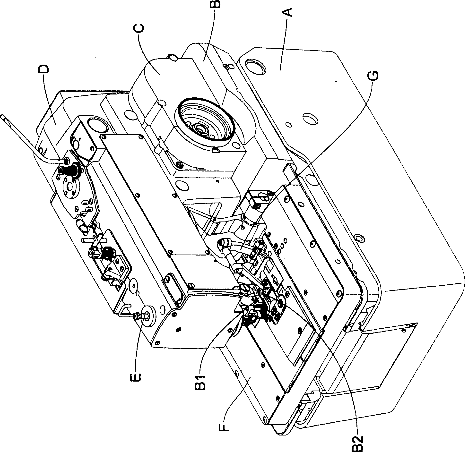
[0046] see Figure 4 Shown is a perspective view of the present invention. The present invention includes a pressing device 1, a tool holder 2 and a cutter 3, the pressing device 1 and the cutter holder 2 are fixed on the bed base B, the cutter 3 is arranged above the cutter holder 2, and is located in the pressing device 1 below the front end. The crimping device 1 includes a rotating shaft 11, and an operating rod 12 whose shaft is arranged on the rotating shaft 11. A clamping screw 13 is used to fix a crimping block 14 at the front end of the operating rod 12. The bottom surface of the crimping block 14 is a flat crimping surface. 140. The operating rod 12 is centered on the rotating shaft 11 and can rotate, so that the press-cut block 14 rotates downward to engage the cutter 3 to cut the cloth. ...


PUM


Abstract

The invention relates to a chip discharging device of a button hole of a button. The chip discharging device is characterized in that a pressing-cutting block in a pressing-cutting device is provided with a movable extruding rod; when the pressing-cutting block declines and is jointed with a cutting tool at the lower part to cut off the cloth, the movable extruding rod applies local extrusion to the cloth to lead the cloth to be in tight state so as to be beneficial to cutting off; and the buttonhole-shaped cloth chips generated after being cut off are extruded into a through hole of the cutting tool and are discharged downwards, thus separating the cloth chips from the cloth assuredly and avoiding the cloth chips from being sewn into the cloth so as to improve the sewing quality.

Description

technical field [0001] The invention relates to a chip discharge device on a sewing machine, in particular to a chip discharge device for buttonholes on a sewing machine, that is, a discharge device for chips generated after buttonhole holes are processed on cloth. Background technique [0002] General buttonholes, except the inline buttonholes, also have so-called buttonholes with keyholes. Button keyholes are straight-line hole fronts connected with a larger approximate circular keyhole. Button keyholes are made by such as figure 1 The sewing machine shown is produced. The sewing machine is equipped with a bed base B on a base A. The bed base B is provided with a transmission unit C and an arm D. The front end of the arm D is provided with a needle bar E. In the vicinity of the needle bar E on B, there is a mobile table F that can move in the X and Y coordinate directions, and one end of the mobile table F is provided with a pressing device G that can press the cloth. Wh...

Claims


Application Information

Patent Timeline
IPC IPC(8): D05B37/02D05B81/00A41H25/00
Inventor 陈冠华
Owner CHEESIANG SEWING MACHINE S H
Why Eureka
Try Eureka