Electrical connection device

An electrical connection device and technology for electrical connection, applied in the direction of two-component connection devices, connections, coupling devices, etc., can solve problems such as unstable electrical connections, and achieve the effects of reduced sliding and reduced wear

Active Publication Date: 2011-10-12
NIHON MICRONICS
View PDF4 Cites 0 Cited by
  • Summary
  • Abstract
  • Description
  • Claims
  • Application Information

AI Technical Summary

Problems solved by technology

Therefore, the conductive part 108 is worn due to repeated energization tests, and the electrical connection between the conductive part 108 and the contact 102 becomes unstable.

Method used


Image

  • Electrical connection device
  • Electrical connection device
  • Electrical connection device

Examples


Embodiment

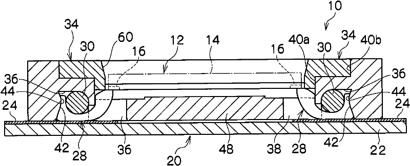
[0054] refer to Figure 1 to Figure 6 , the electrical connection device 10 is used as an auxiliary device in the conduction test (that is, inspection) of the flat-shaped object 12 to be inspected. In the illustrated example, the inspection object 12 is a semiconductor device such as a packaged or molded integrated circuit, an unpackaged or unmolded integrated circuit, or the like.

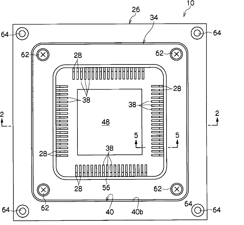
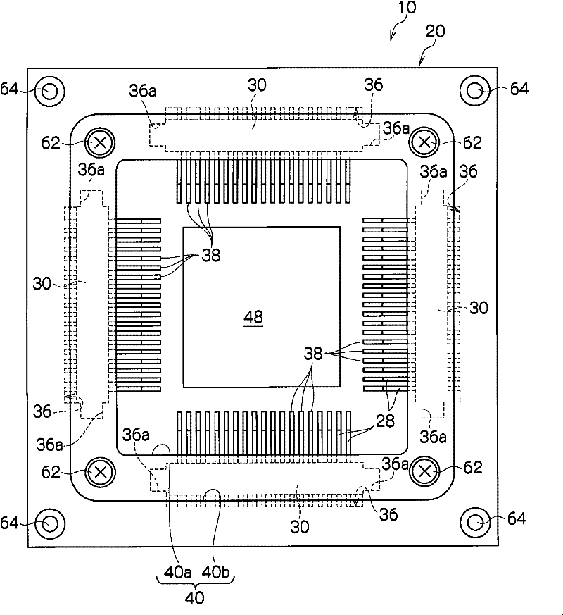
[0055] Such as figure 2 As shown, the object 12 to be inspected has: a main body 14 having a shape like a rectangular plate; and a plurality of electrodes 16 provided on each side of the rectangle on one surface of the main body 14 . The electrodes 16 have a short grid-like shape and are divided into four electrode groups corresponding to each side of the rectangle of the main body 14 in a one-to-one manner, and each electrode group is arranged in parallel.

[0056] Such as figure 2 And as shown in FIG. 5, the substrate 20 such as the wiring substrate for mounting the electrical connection de...


PUM


Abstract

An electrical connection device comprises a housing, a plurality of terminals, and a needle holder. The housing includes a first recess extending in a first direction within a horizontal plane, openinAn electrical connection device comprises a housing, a plurality of terminals, and a needle holder. The housing includes a first recess extending in a first direction within a horizontal plane, opening downward, and having at least a rear side inner facing surface and a plurality of slits extending in a second direction intersecting the first direction within the horizontal plane at intervals in tg downward, and having at least a rear side inner facing surface and a plurality of slits extending in a second direction intersecting the first direction within the horizontal plane at intervals in the first direction. The terminals are disposed in the housing so as to extend from inside the first recess to inside the slits and electrically connect a conductive portion provided on a board to thehe first direction. The terminals are disposed in the housing so as to extend from inside the first recess to inside the slits and electrically connect a conductive portion provided on a board to theelectrode of a device under test. The needle holder is disposed in the first recess. The rear side inner facing surface of the first recess includes a slope sloping with respect to both the horizontalelectrode of a device under test. The needle holder is disposed in the first recess. The rear side inner facing surface of the first recess includes a slope sloping with respect to both the horizontal plane and a vertical plane perpendicular to the horizontal plane so as to extend forward as it extends upward. Each terminal abuts on the slope at at least a part of its rear end. Thus, sliding of thplane and a vertical plane perpendicular to the horizontal plane so as to extend forward as it extends upward. Each terminal abuts on the slope at at least a part of its rear end. Thus, sliding of the terminals with respect to the conductive portion is reduced.e terminals with respect to the conductive portion is reduced.

Description

technical field [0001] The present invention relates to an electrical connection device used in the energization test of a planar object to be inspected such as an integrated circuit, and more particularly to an electrical connection device for electrically connecting a conductive part formed on a substrate and an electrode of the object to be inspected. device. Background technique [0002] In a semiconductor device such as an integrated circuit, a plurality of electrodes protrude from the body of the device. Such a semiconductor device is subjected to an energization test (inspection) using an electrical connection device called a socket. As one type of such an electrical connection device, there is an electrical connection device described in Patent Document 1, for example. [0003] Patent Document 1: Japanese Patent Laid-Open No. 2003-123874 [0004] Such as Figure 7A , Figure 7B as well as Figure 7C As shown, the electrical connection device described in Patent ...

Claims


Application Information

Patent Timeline
Patent Type & Authority Patents(China)
IPC IPC(8): G01R31/26G01R1/073H01R24/00H01R33/76
CPCG01R1/0466G01R31/26H01L22/00
Inventor 大里卫知
Owner NIHON MICRONICS
Why Eureka
Try Eureka