Automatic parking brake device

A technology of braking device and automatic parking, which is applied to foot-actuated starting device, braking action starting device, hydraulic brake transmission device, etc., can solve the problems of increased power consumption and complex structure.

Inactive Publication Date: 2008-12-10
HONDA MOTOR CO LTD
View PDF3 Cites 0 Cited by
  • Summary
  • Abstract
  • Description
  • Claims
  • Application Information

AI Technical Summary

Problems solved by technology

However, not only does the structure become complicated because the electromagnet must be accommodated in the caliper, but power consumption increases because the coil of the electromagnet must be kept energized during the parking brake state.

Method used


Image

  • Automatic parking brake device
  • Automatic parking brake device
  • Automatic parking brake device

Examples


Embodiment 1

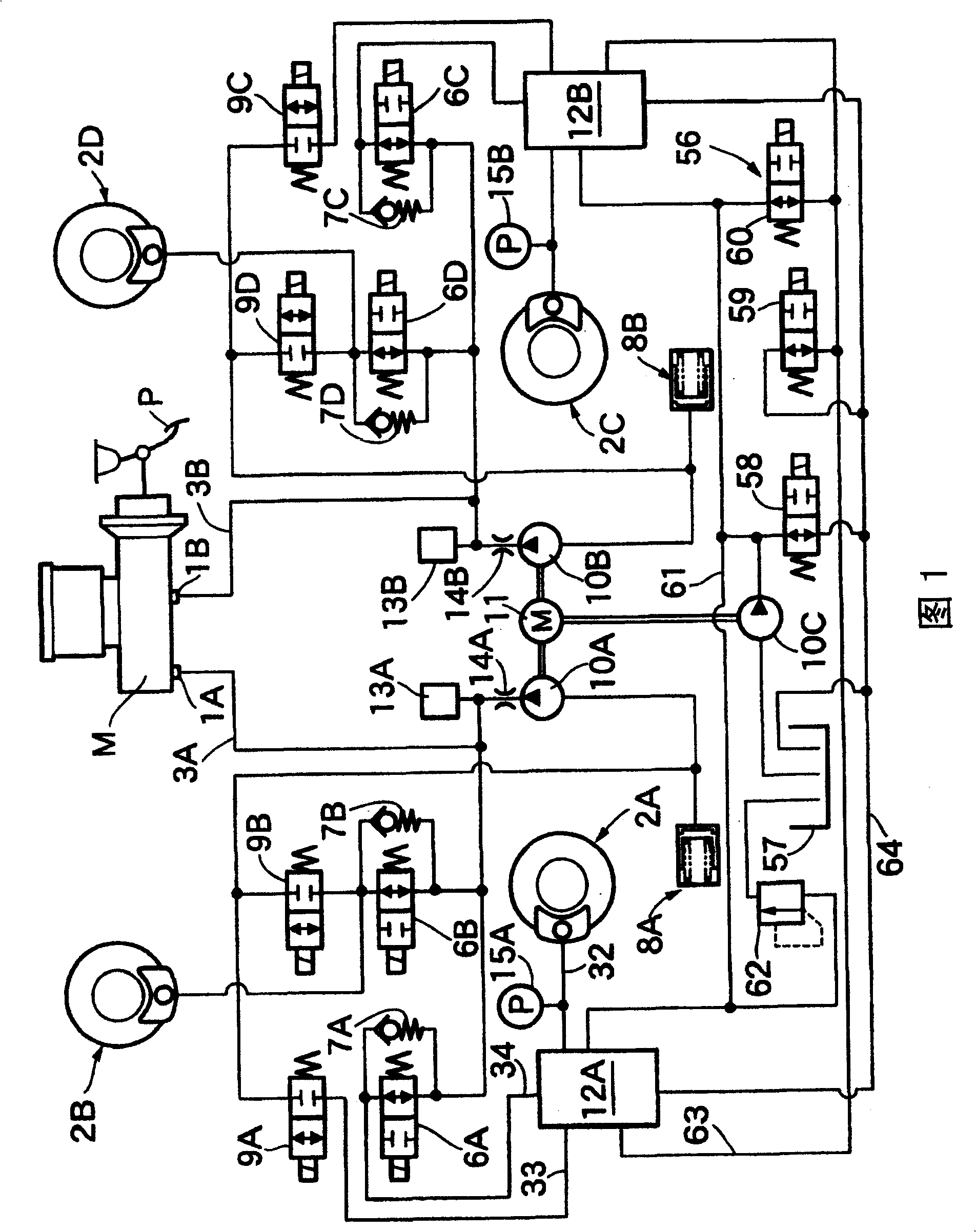
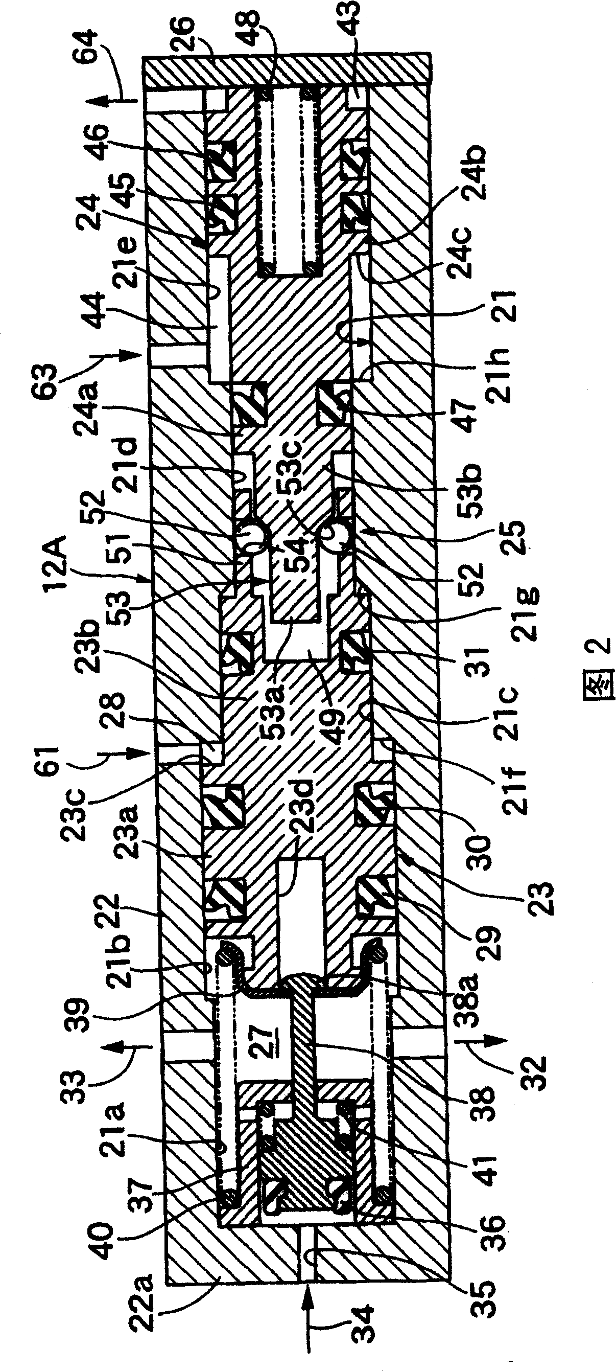
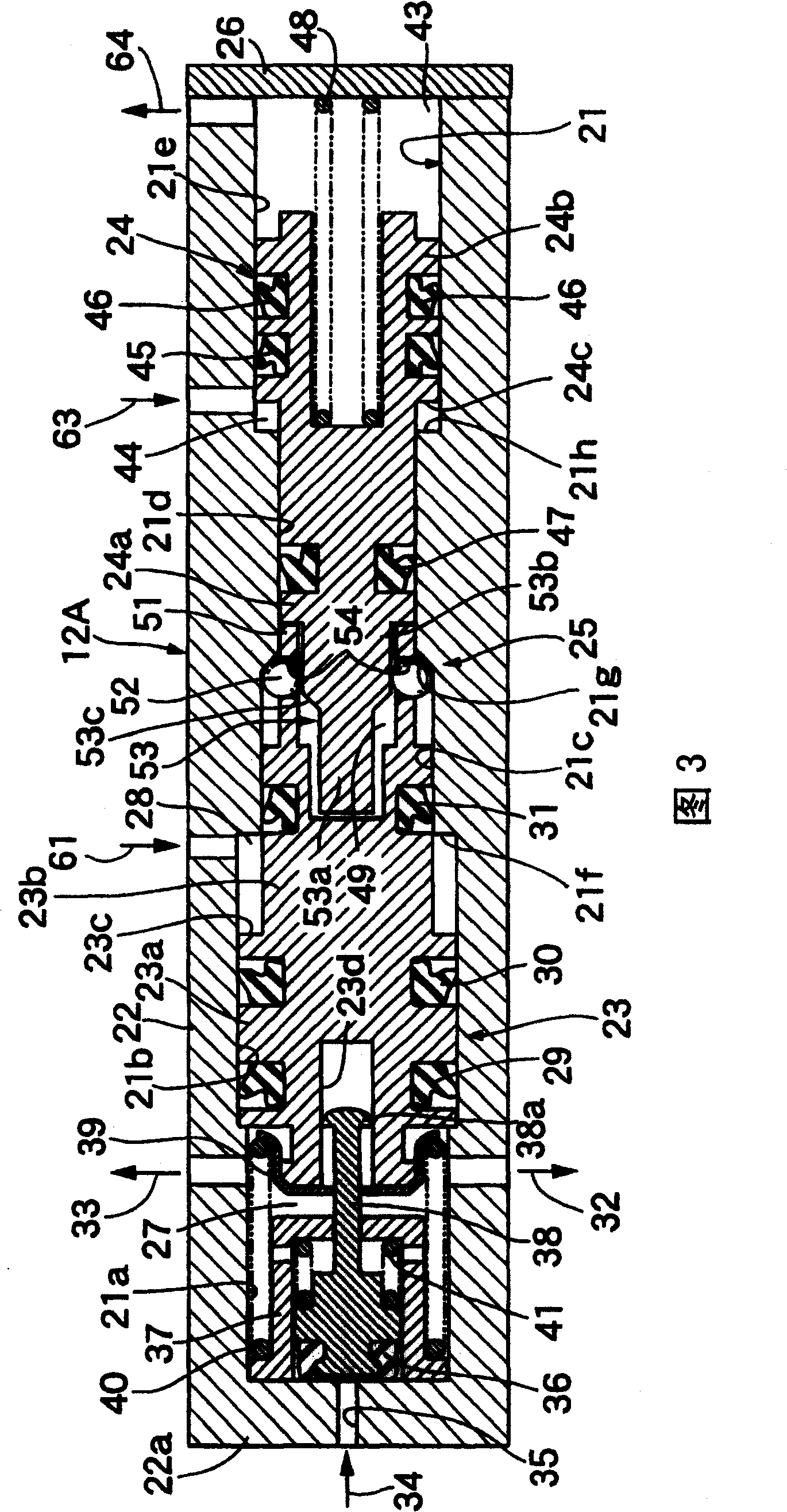
[0024] 1 to 3 show a first embodiment of the present invention.

[0025] First, in FIG. 1 , the tandem-type master cylinder M includes first and second output holes 1A, 1B, and the first and second output holes 1A, 1B can generate a pedaling force applied to the brake pedal P by the driver of the vehicle. As for the corresponding brake hydraulic pressure, the first output hole 1A is connected to the first output hydraulic pressure channel 3A, and the second output hole 1B is connected to the second output hydraulic pressure channel 3B.

[0026] The first output hydraulic passage 3A is connected to the left front wheel wheel brake 2A as a disc brake via the inlet valve 6A of the normally open solenoid valve and the parking actuator 12A, and is connected to the left front wheel brake 2A as a disc brake via the inlet valve 6B of the normally open solenoid valve. The right rear wheel, which is a disc brake, is connected to the wheel brake 2B. In addition, the second output hydrau...

Embodiment 2

[0060] 4 to 6 show a second embodiment of the present invention, and parts corresponding to those of the first embodiment described above are denoted by the same reference numerals.

[0061] First, the first output hydraulic passage 3A connected to the first output port 1A of the main motor M is connected to the hydraulic passage 20A via the shut-off valve 17A which is a normally open solenoid valve, and is connected to the second output port 1B of the main motor M The second output hydraulic passage 3B is connected to the hydraulic passage 20B via a shut-off valve 17B which is a normally open solenoid valve.

[0062] In addition, the first and second reservoir chambers 8A, 8B are connected to the first and second pumps 10A driven by the common electric motor 11 via check valves 19A, 19B that allow the brake fluid to flow to those pumps 10A, 10B The suction sides of the first and second output hydraulic circuits 3A and 3B are connected to the first and second pumps 10A and 10B...


PUM


Abstract

An automatic parking brake device, the parking piston (23) can obtain the parking brake state by moving forward corresponding to the parking control hydraulic pressure on the back, and the parking piston (23) can slide with the casing ( 22) Fitting; its locking mechanism (25) automatically performs a locking action corresponding to the forward movement of the parking piston (23) to mechanically lock the parking piston (23) in the forward position, and simultaneously corresponds to the release of the parking control hydraulic pressure. The locking mechanism (25) is arranged in the housing (22) on the rear side of the parking piston (23); the hydraulic pressure of the hydraulic pressure generating source is controlled by the hydraulic control device, thereby obtaining Control hydraulic pressure for parking and control hydraulic pressure for releasing parking. Thus, the automatic parking brake state can be obtained with a simple structure that does not involve power consumption.

Description

technical field [0001] The present invention relates to an automatic parking brake device, in particular to an automatic parking brake device that automatically obtains a parking brake state without requiring a vehicle driver to operate a parking brake operating member such as a parking brake pedal or a parking brake lever. . Background technique [0002] For example, Patent Documents 1 and 2 and the like disclose a parking brake device that obtains a parking brake state by locking a brake piston in its hydraulic operating state. [0003] Patent Document 1: Japanese Patent Publication No. Hei 10-512947 [0004] Patent Document 2: Japanese Patent Publication No. 2000-504811 [0005] However, in the above-mentioned Patent Document 1, the brake piston is divided into the front brake piston and the rear brake piston, and at the same time, between a transmission member that contacts the front end of the rear brake piston and a blocking plate fixed to the front brake piston A s...

Claims


Application Information

Patent Timeline
Patent Type & Authority Patents(China)
IPC IPC(8): F16D65/20F16D65/32B60T7/04B60T8/32B60T8/34B60T8/42B60T8/48B60T11/20B60T17/16F16D65/14F16D65/18F16D65/28
CPCB60T7/047B60T8/32B60T8/348B60T8/4275B60T8/4872B60T8/489B60T11/20B60T17/16F16D65/18F16D2121/02F16D2127/06F16D2129/02
Inventor 稻垣裕巳
Owner HONDA MOTOR CO LTD
Why Eureka
Try Eureka