Power converter

A power converter and power conversion technology, which is applied in the direction of output power conversion devices, electrical components, AC motor control, etc., to achieve good precision, improve operating performance, and reduce uneven rotation

Inactive Publication Date: 2009-09-02
MITSUBISHI ELECTRIC CORP
View PDF1 Cites 6 Cited by
  • Summary
  • Abstract
  • Description
  • Claims
  • Application Information

AI Technical Summary

Problems solved by technology

In addition, there is a problem that rotation unevenness becomes conspicuous during low-speed driving

Method used


Image

  • Power converter
  • Power converter
  • Power converter

Examples


Embodiment approach 1

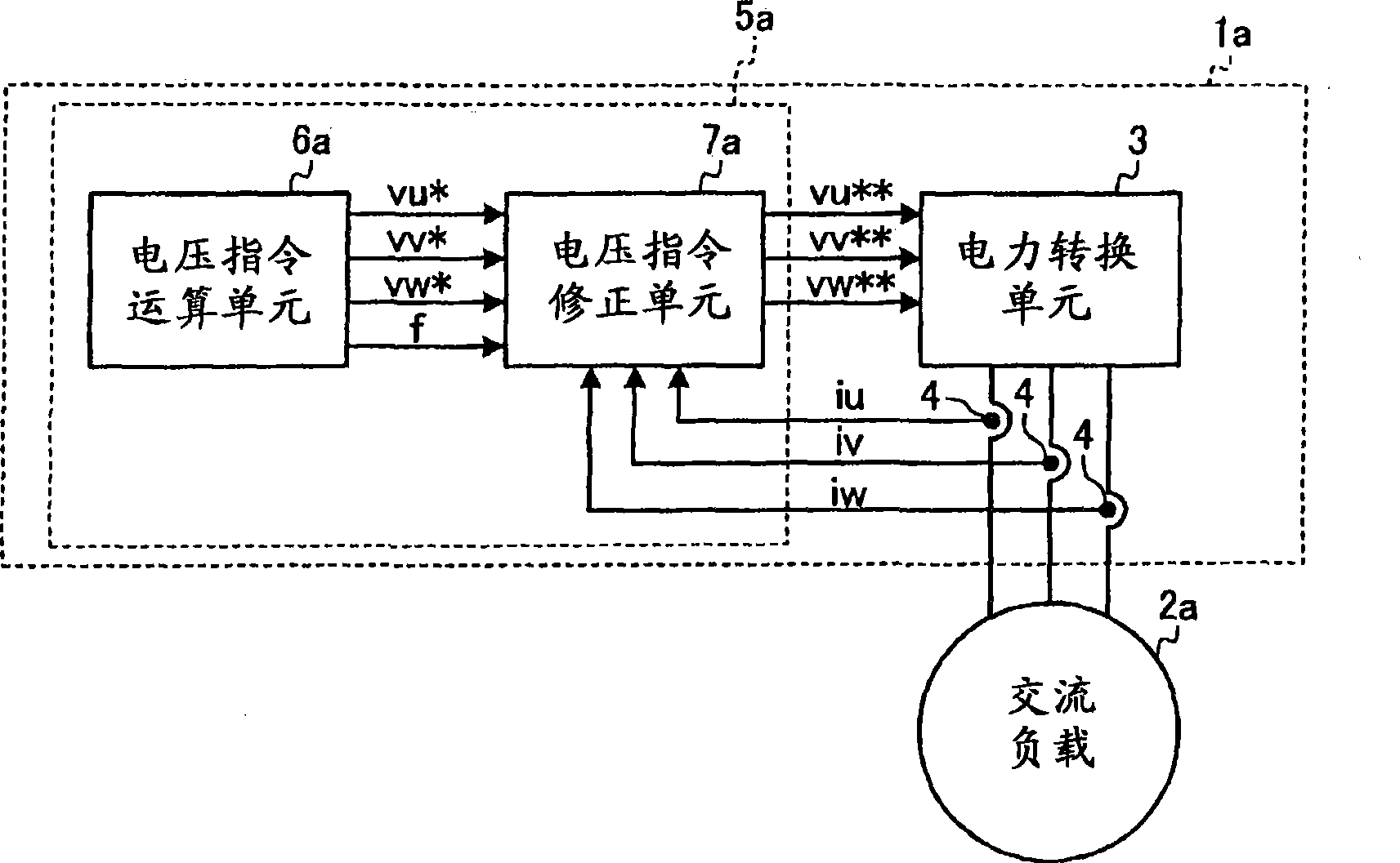
[0051] figure 1 It is a block diagram showing the configuration of the power converter according to Embodiment 1 of the present invention. In Embodiment 1 and the following embodiments, a power converter outputting three-phase AC power is described as an example, but the content is similarly applicable to a power converter outputting single-phase AC power.

[0052] figure 1 The shown power converter 1a includes: a power conversion unit 3 connected to a three-phase AC load 2a; a current detection unit 4; AC power supply control, wherein the control device 5a is composed of a voltage command calculation unit 6a and a voltage command correction unit 7a. The voltage command correction unit 7 a is provided between the output side of the voltage command calculation unit 6 a and the input side of the power conversion unit 3 .

[0053] The power device elements of the upper and lower arms of the power conversion unit 3 are based on the AC voltage command input from the control de...

Embodiment approach 2

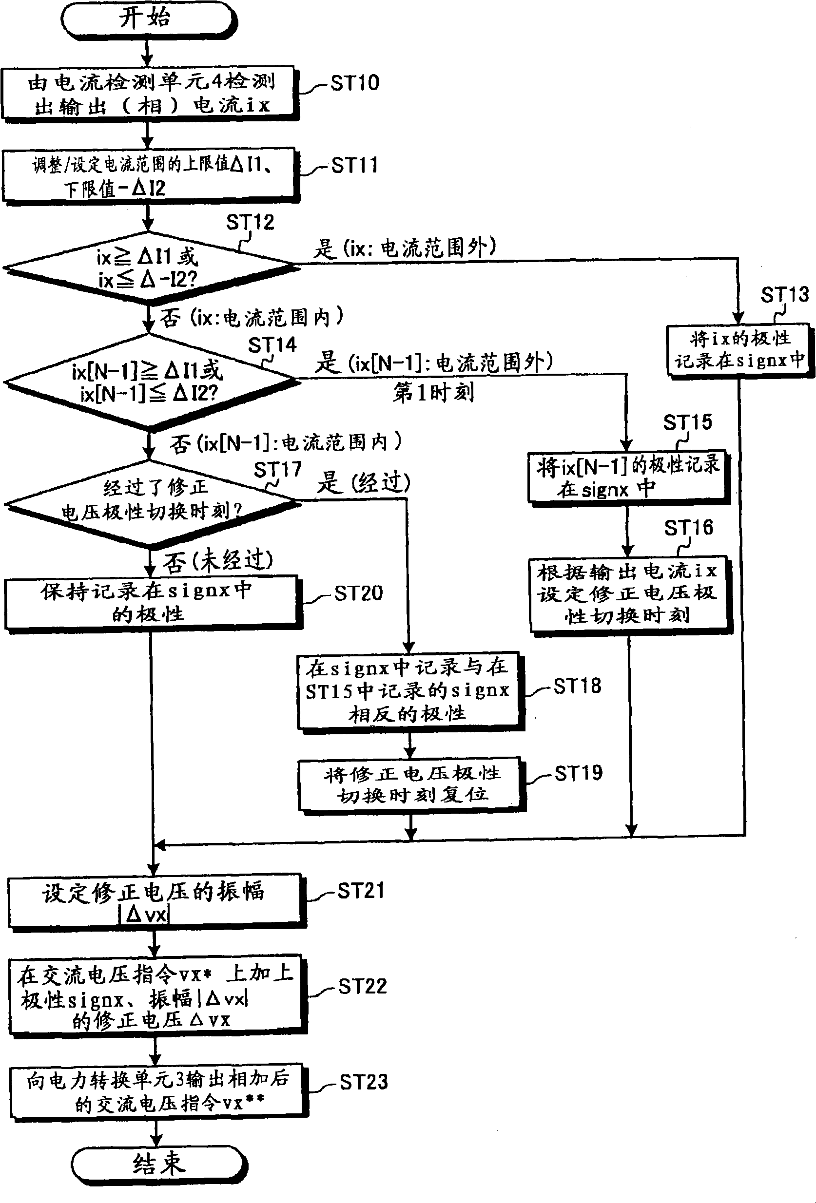
[0115] Figure 8 It is a flowchart explaining the correction operation procedure of the voltage command correction means included in the power converter according to Embodiment 2 of the present invention. exist Figure 8 in, for with figure 2 Processes shown that are the same or equivalent are assigned the same reference numerals. Here, the description will focus on the part related to the second embodiment.

[0116] Such as Figure 8 As shown, the voltage command correction unit included in the power converter of Embodiment 2 is figure 2 In the shown processing procedure, in the process of shifting from ST14 to ST17, if the determination in ST14 is negative (No), the processing of ST30 is performed, and then the process proceeds to ST17.

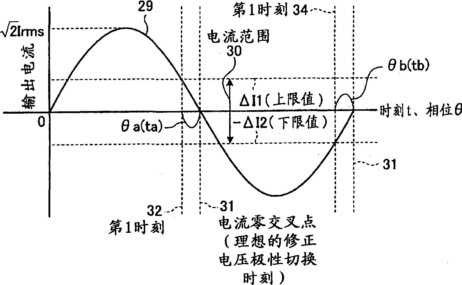
[0117] In ST30, if referring to Figure 7 For explanation, in the period (2) from the first time 32 to the correction voltage polarity switching time 38 , the correction process of the correction voltage polarity switching time 38 i...

Embodiment approach 3

[0124] Figure 9 It is a flowchart explaining the correction operation procedure of the voltage command correction means included in the power converter according to Embodiment 3 of the present invention. exist Figure 9 in, for with figure 2 Processes shown that are the same or equivalent are assigned the same reference numerals. Here, the description will focus on the part related to the third embodiment.

[0125] Such as Figure 9 As shown, the voltage command correction unit included in the power converter of Embodiment 3 is figure 2 In the shown processing procedure, in the process of shifting from ST14 to ST17, if the determination in ST14 is negative (No), the processing of ST40 is performed, and then the process proceeds to ST17.

[0126] In ST40, if referring to Figure 7 For explanation, in the period (2) from the first time 32 to the correction voltage polarity switching time 38 , the correction process of the correction voltage polarity switching time 38 is...


PUM


Abstract

A power converter wherein the voltage error, which is caused by a dead time in the vicinity of the zero cross of an output current, can be accurately corrected and a power converting means can output an AC power in accordance with an AC voltage command. A voltage command correcting means, which is disposed between the power converting means and a voltage command arithmetic means, establishes a predetermined current range including a zero level for a detected output current. At a first time point when the value of the output current gets into the current range, the voltage command correcting means sets, based on the first time point and a frequency (f) (and the output current as well), a time point, at which to switch the polarities of a correction voltage that corrects the AC voltage command arithmetically outputted by the voltage command arithmetic means, to a timing of zero cross of the output current. That is, the switching of the polarities of the correction voltage used to correct the voltage error caused by the dead time is effected at the zero cross of the output current, whereby the correction voltage exhibiting the same polarity as the output current can be used to correct the AC voltage command in the neighborhood of the zero cross of the output current.

Description

technical field [0001] The present invention relates to a power converter for supplying AC power to an AC load. Background technique [0002] In the power converter, the power device elements of the upper and lower arms constituting the power conversion unit provided on the output stage perform switching operations according to the voltage command to generate an AC voltage and output it to the AC load, but to prevent the power device elements of the upper and lower arms from being For the purpose of short-circuiting due to simultaneous conduction, a period is provided to control the power device elements of the upper and lower arms to be in a simultaneous shut-off operation state. This period is called a dead time, and it is known that an error occurs between the voltage command received by the power conversion unit and the voltage actually output to the load by the voltage conversion unit based on this dead time. The error voltage caused by the dead time is a voltage havin...

Claims


Application Information

Patent Timeline
Patent Type & Authority Applications(China)
IPC IPC(8): H02M7/48H02M7/537
CPCH02M7/48H02M7/5395H02P27/08H02M2001/0009H02M1/0009
Inventor 小林贵彦金原义彦吉村学
Owner MITSUBISHI ELECTRIC CORP
Why Eureka
Try Eureka