
Electric vacuum cleaner

A vacuum cleaner, electric technology, applied in the direction of vacuum cleaners, suction filters, cleaning equipment, etc., can solve the problems of exhaust air blowing to the user, the exhaust air flow rate increases, and the amount of negative ions cannot be increased, so as to increase the amount of negative ions and improve efficiency effect

Inactive Publication Date: 2011-08-03
PANASONIC CORP
View PDF1 Cites 0 Cited by
  • Summary
  • Abstract
  • Description
  • Claims
  • Application Information

AI Technical Summary

Problems solved by technology

But in this way, the flow velocity of the exhaust airflow discharged from the vacuum cleaner body 3 will rise, which can blow away the dust on the ground that has not been vacuumed and the dust attached to the furniture, and the exhaust airflow may also blow away. It is not ideal from a hygienic point of view
[0008] In addition, although the method of arranging multiple discharge electrodes close to each other in one air duct can also be considered, the experimental results show that the amount of negative ions generated is also easily saturated, and the amount of negative ions generated cannot be increased.

Method used


Image

  • Electric vacuum cleaner
  • Electric vacuum cleaner
  • Electric vacuum cleaner

Examples


Embodiment Construction

[0023] An embodiment of the present invention will be described in detail below with reference to the accompanying drawings. It should be pointed out that such examples do not limit the scope of the present invention.

[0024] (Example)

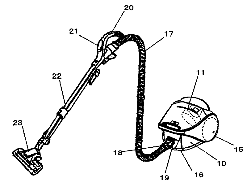
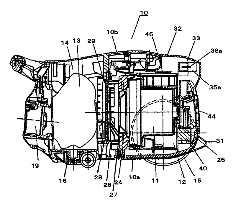
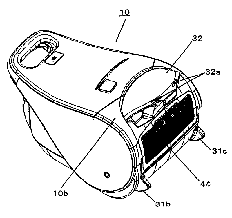
[0025] Use below Figure 1 to Figure 6 The electric vacuum cleaner in this embodiment will be described in detail.

[0026] Such as figure 1 and figure 2 As shown in , the rear part of the vacuum cleaner body 10 is provided with an electric fan chamber 12 with a built-in electric fan 11, and the front part is provided with a dust collection chamber 14, and a detachable dust collector for catching / collecting dust is installed in the dust collection chamber 14. dust bag13. Two freely rotatable wheels 15 for walking are installed on both sides of the rear bottom of the vacuum cleaner body 10, and small rollers 16 that are also used for walking are installed on the front bottom surface. The front portion of the vacuum cleaner body 10 is p...


PUM


Abstract

The present invention provides an electric vacuum cleaner with excellent dust collecting efficiency, which can effectively increase negative ions generated from the discharged electrode, without increasing exhaust air flow rate of the vacuum cleaner body. The vacuum cleaner includes: an electric fan chamber of an electric fan for storing produced dust suction air flow; a dust collecting room for capturing / collecting dust; the first and second air discharge channels (35a, 36b) for discharging exhaust air of the electric fan to the outside; discharged electrodes for emitting negative ions respectively equipped on the first and second air discharge channels; a high-voltage circuit for exerting high voltage on the discharged electrode. Because the discharged electrodes are respectively equipped in the separated first and second air discharge channels (35a, 36b), the amount of generated negative ions corresponding to the number of the discharged electrode is effectively increased.

Description

technical field [0001] The present invention relates to an electric vacuum cleaner, and more particularly, to an electric vacuum cleaner provided with an ion generating device capable of generating ions. Background technique [0002] Existing electric vacuum cleaners of this kind are generally as Figure 7 (for one example, refer to Japanese Patent Laid-Open No. 2004-33454). [0003] Figure 7 It is a sectional view of the existing electric vacuum cleaner shown in the above-mentioned reference. Figure 7 Among them, 1 is an ion generating device capable of producing negative ions, and an ion electrode 2 is provided. The ion generator 1 is arranged on the rear upper part of the vacuum cleaner body 3 or on the upper part of the electric blower 4 that generates the dust suction airflow. 7 is a high-voltage power supply device for applying a high voltage of 5 kV to the ion electrode 2 . [0004] The rear of the vacuum cleaner body 3 is provided with an ion discharge port 5 for...

Claims


Application Information

Patent Timeline
Patent Type & Authority Patents(China)
IPC IPC(8): A47L5/12A47L9/10
Inventor 锦织环古贺理基福嶋雅一
Owner PANASONIC CORP
Learn More