Multi-drill-bit graphite machining equipment

A processing equipment and multi-drill technology, applied in the direction of stone processing equipment, stone processing tools, work accessories, etc., can solve the problems of tool cooling, processing dust, and high processing cost of large processing equipment

Active Publication Date: 2014-12-24
于海东
View PDF6 Cites 3 Cited by
  • Summary
  • Abstract
  • Description
  • Claims
  • Application Information

AI Technical Summary

Problems solved by technology

But these are generally suitable for small holes, but deep hole multi-hole drilling, especially when it involves several deep holes with a depth of 500-600mm and a diameter of more than 100mm, is a technical problem for single-hole processing. Problems such as tool cooling and heat dissipation and high torque on the tool
For example, when processing several uniformly arranged Φ100×800mm deep holes (including through holes and blind holes) in the same graphite crucible, ordinary lathes, mechanical equipment and their tools cannot be processed effectively, and special deep holes of the same diameter are required here. Hole drill or boring tool with sufficient length, considering the diameter and length of the tool and the stress during processing, general lathes, boring machines and drilling machines cannot be installed or modified well; the cost of large-scale machining is high, and the graphite crucible is processed. Dust generated will pollute mechanical equipment
[0004] At the s...

Method used


Image

  • Multi-drill-bit graphite machining equipment
  • Multi-drill-bit graphite machining equipment
  • Multi-drill-bit graphite machining equipment

Examples


Embodiment Construction

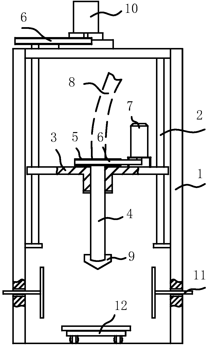
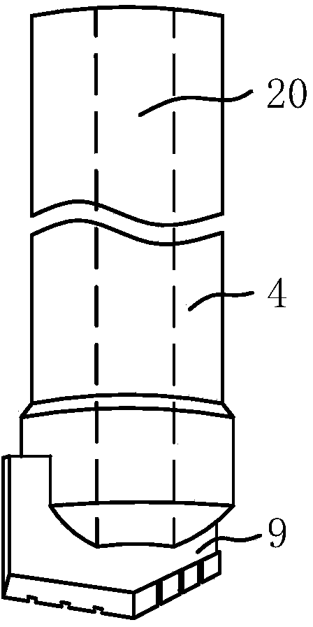
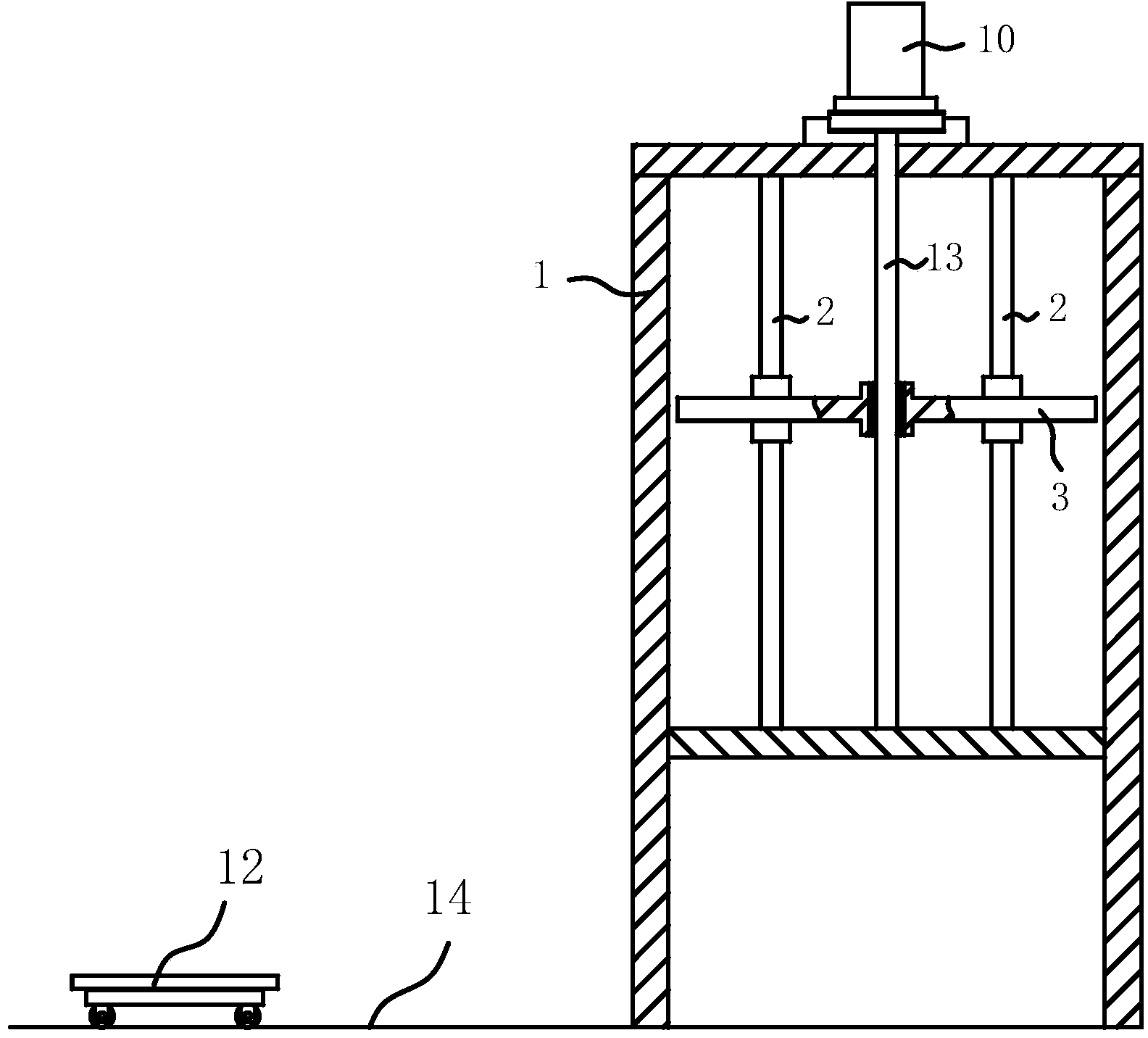
[0028] The invention discloses a multi-drill graphite processing equipment, comprising a vertical frame 1 and a lifting platform 3 installed on the frame 1, the lifting platform 3 is arranged on the light rod 2 on the upper part of the frame 1 and passes through the screw 13 rotates to drive lifting, the screw 2 is connected to the lifting motor 10; the lifting platform 3 is vertically installed with a main shaft 4 and several auxiliary shafts 21, the main shaft 4 is arranged at the center of the lifting platform 3, and several auxiliary shafts 21 are evenly surrounded Around the main shaft 4, the main shaft 4 and the auxiliary shaft 21 are connected by a gear 22; the main shaft 4 and the auxiliary shaft 21 are respectively provided with through holes 20 along the axial direction; the upper end of the main shaft 4 is provided with a pulley 5 and passed through a belt 6 is connected to the driving motor 7 installed on the upper end surface of the lifting platform 3, and the uppe...


PUM


Abstract

The invention relates to the field of multi-drill-bit graphite product drilling equipment. The multi-drill-bit graphite machining equipment comprises a vertical frame and a lifting platform arranged on the frame, wherein the lifting platform is arranged on a polished lever on the upper part of the frame, and is driven to ascend and descend through the rotation of a lead screw; the lead screw is connected with a lifting motor; a main revolving shaft and a plurality of auxiliary revolving shafts are vertically arranged on the lifting platform; the main revolving shaft is arranged in the center of the lifting platform; the auxiliary revolving shafts uniformly surround the periphery of the main revolving shaft; the main revolving shaft and the auxiliary revolving shafts are connected through a gear; the main revolving shaft and the auxiliary revolving shafts are provided with through holes along the axis direction respectively; the upper end part of the main revolving shaft is provided with a belt wheel, and is connected with a driving motor arranged on the upper end face of the lifting platform through a belt; the upper end parts of the main revolving shaft and the auxiliary revolving shafts are connected with a dust sucking device respectively through suction pipes; plate-like tools are arranged on the lower end heads of the main revolving shaft and the auxiliary revolving shafts; the revolving shaft through holes are isolated symmetrically by the tools. The multi-drill-bit graphite machining equipment is simple in structure, has a good dust-removing effect, and is equipment special for deep-hole machining of large and medium-sized graphite crucibles.

Description

technical field [0001] The invention relates to the field of drilling equipment for graphite products with multiple drill bits, in particular to a multi-drill bit processing equipment which has a dust-absorbing function and simultaneously processes porous deep holes and large holes. Background technique [0002] Graphite crucible has good thermal conductivity and high temperature resistance. During high temperature use, the thermal expansion coefficient is small, and it has certain strain resistance to rapid heating and rapid cooling. It has strong corrosion resistance to acid and alkaline solution and has excellent chemical stability. Graphite crucibles are widely used in the smelting of alloy tool steel and the smelting of non-ferrous metals and their alloys in metallurgy, casting, machinery, chemical and other industrial sectors because of the above excellent properties. And has a good technical and economic effect. [0003] At present, for the deep hole processing of p...

Claims


Application Information

Patent Timeline
IPC IPC(8): B28D1/14B28D7/02
Inventor 于海东
Owner 于海东
Why Eureka
Try Eureka